Altronix WayPoint-7 Installation Instructions User Manual
Page 2
- 2 -
DC Outdoor
Overview:
These Altronix High Current Outdoor Power Supply/Chargers provide 12VDC or 24VDC and are designed to be
conveniently located where power is required.
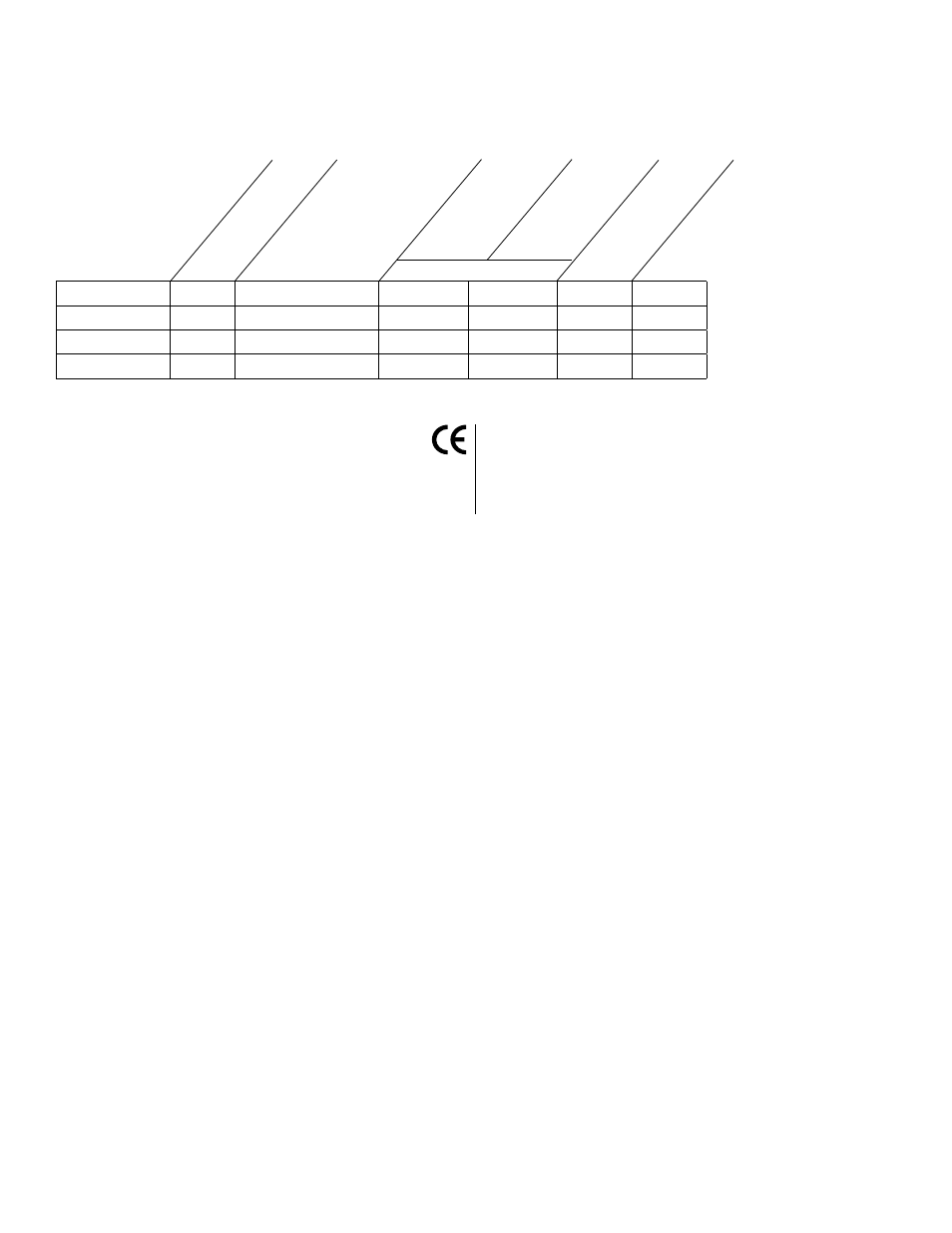
WayPoint DC Reference Chart:
WayPoint-3
2.5 amp 12VDC or 24VDC CLOSED
OPEN
0.95 amp 0.6 amp
WayPoint-5
4 amp 12VDC or 24VDC CLOSED
OPEN
0.95 amp 0.6 amp
WayPoint-7
6 amp 12VDC or 24VDC CLOSED
OPEN
1.9 amp
N/A
WayPoint-7V
6 amp 12VDC or 24VDC CLOSED
OPEN
N/A
0.95
Specifications:
Installation Instructions:
Wiring methods shall be in accordance with the National Electrical Code/NFPA 70/NFPA 72/ANSI, and with all local
codes and authorities having jurisdiction.
1. Remove back plane from enclosure prior to mounting (do not discard hardware).
2. Mark and drill desired inlets on the enclosure to facilitate wiring (Fig. 1, pg. 3).
3. Mount unit in desired location. Mark and drill holes to line up with the top and bottom holes of the enclosure flange.
Secure enclosure with appropriate fasteners (Fig. 5 & 5a, pg. 7 and Fig. 6, pg. 8).
4. Mount back plane to enclosure with hardware.
5. Set power switch to the OFF position (Fig. 2b, pg. 4, Fig. 3b, pg. 5, Fig. 4b, pg. 6).
6. Connect AC power (115VAC) to terminals marked [L & N], connect ground to terminal
marked [G] (Fig. 2-4, pgs. 4-6). Use 18 AWG or larger for all power connections (Battery, DC output).
7. Select the desired DC output voltage by setting SW1 to the appropriate position (Reference Chart above)
(Fig. 2a, pg. 4, Fig. 3a, pg. 5, Fig. 4a, pg. 6).
8. Set power switch to the ON position (Fig. 2b, pg. 4, Fig. 3b, pg. 5, Fig. 4b, pg. 6).
9. Measure output voltage at terminals marked [--- DC +] before connecting devices (Fig. 2c, pg. 4, Fig. 3c, pg. 5,
Fig. 4c, pg. 6). This helps avoid potential damage.
Note: Power supplies mounted in weatherproof enclosures should be derated by approximately
50% due to harsh environmental conditions.
10. Set power switch to the OFF position (Fig. 2b, pg. 4, Fig. 3b, pg. 5, Fig. 4b, pg. 6).
11. Connect devices to be powered to terminals marked [--- DC +] (Fig. 2c, pg. 4, Fig. 3c, pg. 5, Fig. 4c, pg. 6).
12. Connect optional stand-by battery to terminals marked [+ BAT --- ] battery leads included
(a separate enclosure is needed for batteries) (Fig. 2c, pg. 4, Fig. 3c, pg. 5, Fig. 4c, pg. 6).
Note: When batteries are not used, a loss of AC will result in a loss of output voltage.
13. Set power switch to the ON position (Fig. 2b, pg. 4, Fig. 3b, pg. 5, Fig. 4b, pg. 6).
14. Upon completion of wiring, secure enclosure door with latches and optional lock.
Caution: Equipment to be installed / serviced by authorized / trained personnel only.
Shut branch circuit power before installing / servicing equipment.
WARNING: To reduce the risk of fire or electric shock.
This installation should be made by qualified service personnel and should conform to all local codes
and in accordance with the National Electrical Code.
• CE Compliant (except WayPoint-7/7V).
• AC and DC power LED indicators.
• Ease of installation saves time and
eliminates costly labor.
• Includes battery leads.
• NEMA 4/4X, IP66-11 Rated Outdoor Enclosure.
• Operating Ambient Temperature: -20º C to 50º C.
Enclosure Dimensions (H x W x D):
13.31” (338.074mm) x 11.31” (287.274mm) x
5.59” (141.986mm)
Altronix
Model
Number
Total
Output
Current
(Power)
115VAC/60Hz
Input
Current
Draw
230VAC/50Hz
Input
Current
Draw
Output
Voltage
12VDC
24VDC
SW1