Facp hook-up diagrams, Factory installed jumper, 30vdc from facp signal circuit – Altronix Maximal3R Installation Instructions User Manual
Page 9: Normally open [no] reset switch, Normally closed [nc] dry trigger input
Maximal Rack Access Power Controllers (Fused)
- 9 -
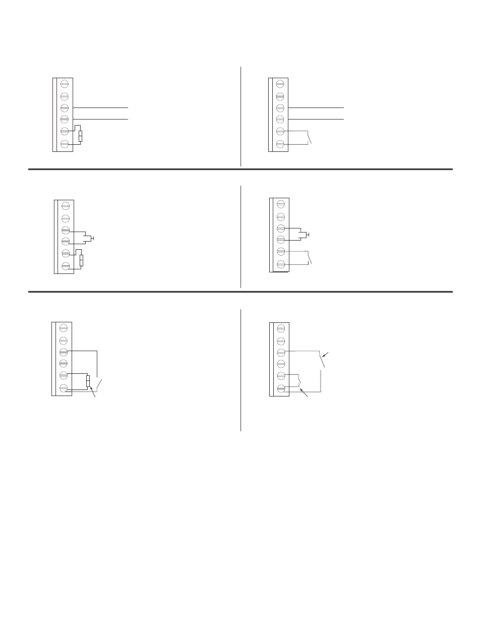
FACP Hook-Up Diagrams
Polarity Reversal Input from FACP Signal Circuit Output
(Polarity is referenced in alarm condition)
Fig. 6
GND
IN8
GND
5-30VDC
from FACP
Signal Circuit
Factory Installed
Jumper
--
+
1
2
FACP
RESET
GND
IN8
GND
5-30VDC
from FACP
Signal Circuit
--
+
Normally Open [NO]
Reset Switch
1
2
FACP
RESET
Non-Latching
Normally Closed Input from FACP
Fig. 7
GND
IN8
GND
Factory Installed
Jumper
Normally Closed [NC] Dry
Trigger Input
1
2
FACP
RESET
GND
IN8
GND
Normally Closed [NC] Dry
Trigger Input
Normally Open [NO]
Reset Switch
1
2
FACP
RESET
Normally Open Input from FACP
Fig. 8
1
2
GND
FACP
IN8
RESET
GND
Normally Open [NO] Dry
Trigger Input
Factory Installed
Jumper
GND
IN8
GND
Normally Open [NO]
Dry Trigger Input
Normally Open [NO]
Reset Switch
1
2
FACP
RESET
Fig. 9
Fig. 10
Fig. 11
Latching
Non-Latching
Latching
Non-Latching
Latching
- NetWay3012 Installation Instructions (2 pages)
- HubWay 16Di Data Sheet (2 pages)
- Maximal77 Installation Instructions (20 pages)
- HubWay Dvi Data Sheet (1 page)
- HubWay Av2 Data Sheet (1 page)
- PD4CB Installation Instructions (1 page)
- ACM4CB Data Sheet (2 pages)
- VertiLine63D Data Sheet (2 pages)
- eBridge16CR Installation Instructions (8 pages)
- LPS3WP12 Data Sheet (2 pages)
- VertiLine246D Data Sheet (2 pages)
- T24130D Data Sheet (1 page)
- eBridge1PCRTX Data Sheet (2 pages)
- RB5 Installation Instructions (1 page)
- Tempo2 Data Sheet (1 page)
- BC600G Data Sheet (1 page)
- eBridge1CRT Data Sheet (2 pages)
- AL400ULB Data Sheet (1 page)
- PT2724 Installation Instructions (8 pages)
- OLS180 Installation Instructions (2 pages)
- HubWay 8CD Data Sheet (2 pages)
- AL175ULB Data Sheet (1 page)
- StrikeIt2 Installation Instructions (8 pages)
- LPD Data Sheet (1 page)
- eBridge4SK Installation Instructions (8 pages)
- LPS3AC Installation Instructions (2 pages)
- T2428100 Data Sheet (1 page)
- TP1650 Data Sheet (1 page)
- T2885D Data Sheet (1 page)
- T2428175 Installation Instructions (1 page)
- T1656 Installation Instructions (1 page)
- SMP3 Data Sheet (1 page)
- RBR1224 Data Sheet (1 page)
- HubWay LD16D Data Sheet (2 pages)
- eFlow102NX16D Installation Instructions (16 pages)
- T24175C Data Sheet (1 page)
- Maximal5D Data Sheet (2 pages)
- Maximal7 Installation Instructions (16 pages)
- HubWay 8CDS Data Sheet (2 pages)
- eFlow4NX8D Installation Instructions (16 pages)
- MOM5C Data Sheet (1 page)
- eBridge16PCRX Installation Instructions (8 pages)
- HubWay EX16SP Data Sheet (2 pages)
- T24130C Installation Instructions (1 page)
- Maximal5 Data Sheet (2 pages)