13 connections, display and control elements, 1 serial interface – VEGA INSYS Modem GPRS 5.0 User Manual
Page 106
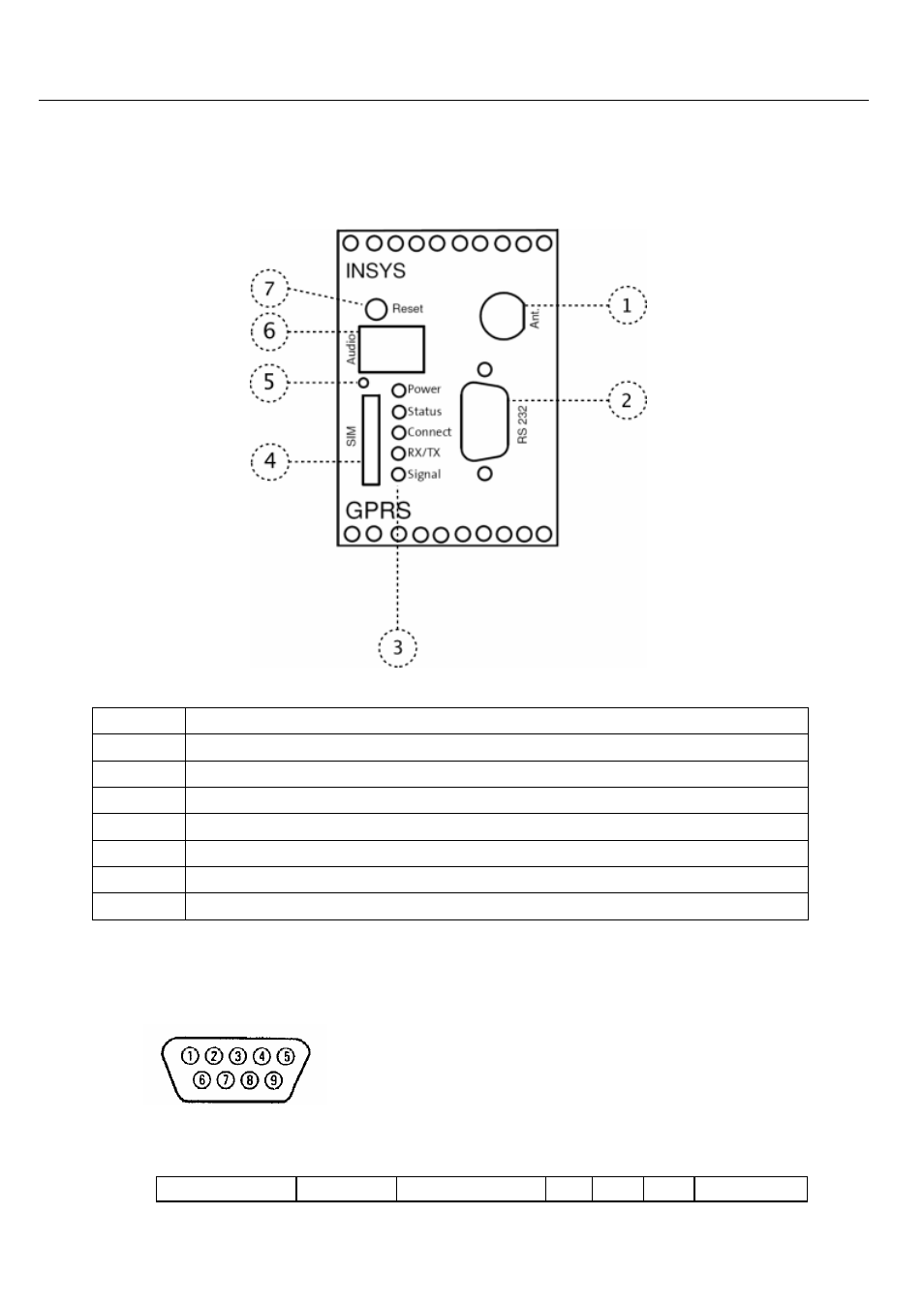
Connections, Display and Control Elements
INSYS GPRS 5.0 serial
106
13
Connections, Display and Control Elements
Position
Description
1
Antenna connection
2
RS232 interface connection
3
LEDs
4
SIM card slot
5
SIM card eject button
6
- not used -
7
Reset key
13.1
Serial Interface
Layout of the 9-pin D-SUB jack
Description of the signals on the 9-pin D-SUB connector on DCE side:
9-pin D-Sub DCE
Description
Function
CCITT EIA
DIN E/A DCE to DTE