VEGA VEGADIF 65 4 … 20 mA_HART User Manual
Page 36
36
5 Connecting to power supply
VEGADIF 65 • 4 … 20 mA/HART
36128-EN-130417
3
2
1
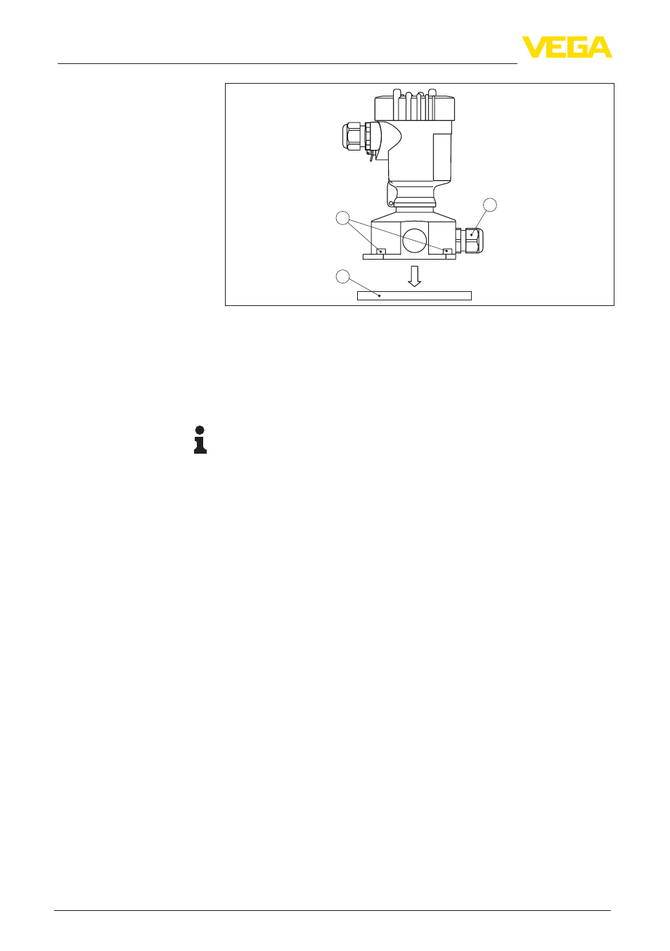
Fig. 35: Components of the external housing
1 Screws
2 Wall mounting plate
3 Cable gland
3. Loop the connection cable through the cable entry on the housing
base
1)
Information:
The cable gland can be mounted in three positions each displaced
by 90°. Simply exchange the cable gland against the blind plug in the
suitable thread opening.
4. Connect the wire ends as described under "Single/Double cham-
ber housing" according to the numbering
5. Connect the screen to the internal ground terminal, connect the
outer ground terminal above on the housing to potential equalisa-
tion
6. Tighten the compression nut of the cable entry. The seal ring must
completely encircle the cable
7. Attach the mounting plate again and tighten the screws
The electrical connection of the sensor to the external housing is
finished.
1)
The connection cable comes pre-assembled. If necessary, shorten it to the
requested length, cut the breather capillaries clean. Remove approx. 5 cm of
the cable mantle, strip approx. 1 cm insulation from the ends of the individual
wires. After shortening the cable, fasten the type plate with support back on
the cable.