4 wiring plan, 1 adjustment system, 2 setup steps – VEGA VEGAMET 381 Ex User Manual
Page 25
25
6 Setup with the integrated display and adjustment unit
VEGAMET 381 Ex • 4 … 20 mA signal conditioning instrument
30418-01-131025
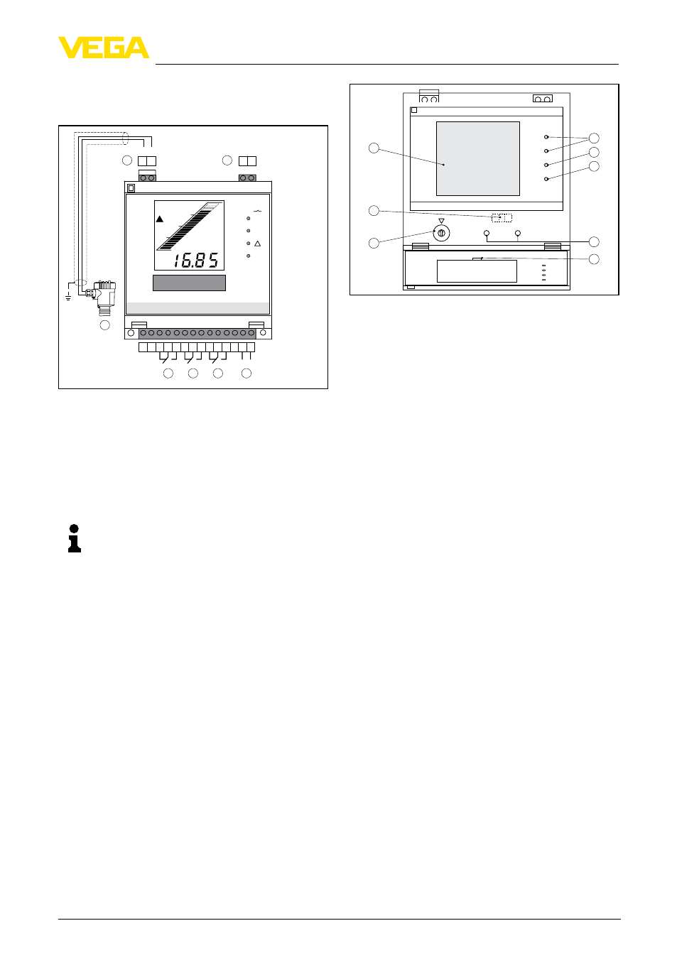
5.4 Wiring plan
Overview
+ -
1 2
+ -
3 4
18 17 16 15 14 13 12 11 10 9 8 7 6 5
N- L1+
on
1
2
1
2
%
1
2
3
4
5
6
7
Abb. 15: Wiring plan with two-wire sensor
1 Measurement data input, optionally available with
sensor power supply
2 Current output
3 Fail safe relay
4 Relay 2
5 Relay 1
6 Voltage supply
Tipp:
For parameter adjustment of connec-
ted HART sensors, the sockets are
integrated in the terminals of the meas.
data input. A VEGACONNECT can be
directly plugged in without the need of
an additional HART resistor.
6 Setup with the integrated
display and adjustment
unit
6.1 Adjustment system
The integrated display and adjustment unit is
for measured value display, adjustment and
diagnosis ofVEGAMET 381 Ex. Indication and
adjustment is carried out in the front via a clear
LC-display and a function switch as well as two
keys.
To open the cover, insert a screwdriver in the
two slots on the top and turn it slightly.
012
34
567
89
AB
C
-
+
1
2
1
3
8
7
6
5
2
4
Abb. 16: Display and adjustment elements
1 Status indication operating relay 1 and 2
2 Status indication fail safe relay
3 Status indication operation
4 [+/-] adjustment keys
5 Insertable tag for identification of the measure-
ment loop
6 Function switch
7 Mode switch for sensor input (active/passive) on
the rear of the instrument
8 LC display
Key functions
•
[Function switch] for selection of:
– Adjustment
– Relay switching points
– Indication scaling
– Current output
– Integration time
– Offset correction
•
[+/-] key:
– Change value of the parameters
By pushing the [+/-] key, you change the indivi-
dual parameters of the selected function. In this
phase, the processed parameter is flashing. By
briefly pushing the two keys simultaneously, you
save your settings. "Save" is briefly displayed.
6.2 Setup steps
Setup
Setup comprises mainly the adjustment of the
measurement loop. A scaling of the measured
value for the LC display and the adaptation of
the relay switching points are further settings.
Additional setup steps would be, if necessary,
setting an integration time (damping) to steady
the measured value or modifying the current