VEGA VEGAMET 625 User Manual
Page 18
18
6 Setup with the integrated display and adjustment unit
VEGAMET 625 • Double channel HART
28970-EN-130701
After being switched on, VEGAMET 625 first of all carries out a short
self-check. The following steps are carried out:
•
Internal check of the electronics
•
indication of the instrument type, firmware version as well as the
instrument TAG (instrument name)
•
The output signals jump briefly to the set fault value
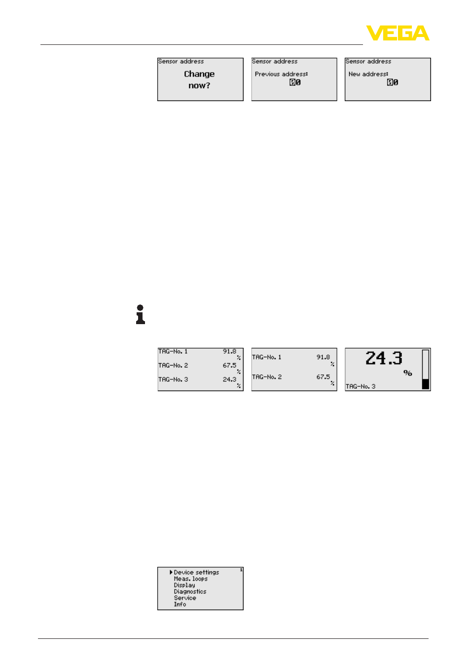
After the assignment of the addresses to the sensors, the current
measured values will be displayed and outputted.
As requested, the measured value display shows the individual
measurement loops separately or in a joint overview. The respective
digital display value, the measurement loop name (meas. loop TAG)
and the unit are shown. With the separate presentation, an analogue
bar graph is also displayed and the measured values appear in big-
ger font size. By pushing the [>] key, you move between the different
indicating options.
Note:
Depending on the configuration and use of all measurement loops,
the cycle time for the measured value transmission can take up to five
seconds.
By pushing [OK] you move from the measured value indication to the
main menu.
The main menu is divided into six areas with the following functions:
•
Device settings: Includes the device-TAG, settings for network
connection such as date/time setting, …
•
Measurement loop: Includes settings for input selection, adjust-
ment, damping, linearization, scaling, outputs, …
•
Display: Includes settings to the displayed measured value
•
Diagnosis Includes information to the device status, error mes-
sages
•
Service Includes simulation, reset, PIN, selectable language,
sensor address, …
•
Info: Shows serial number, software version, last change, instru-
ment features, MAC addr., …
Switch-on phase
Measured value indica-
tion
Main menu