5 menu schematic, Display, Optional settings – VEGA VEGASON 61 Foundation Fieldbus User Manual
Page 31
31
6 Set up with the display and adjustment module PLICSCOM
VEGASON 61 • Foundation Fieldbus
28790-EN-130417
Peak value
The min. and max. distance and temperature values are reset to the
actual value.
Additional adjustment and diagnosis options such as e.g. scaling,
simulation or trend curve presentation are shown in the following
menu schematic. You will find a detailed description of these menu
items in the operating instructions manual "Display and adjustment
module".
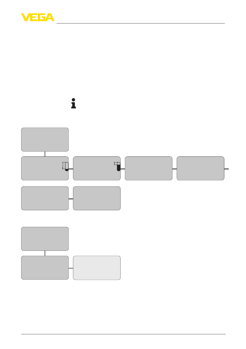
6.5 Menu schematic
Information:
Depending on the version and application, the highlighted menu
windows may not always be available.
Basic adjustment
▶
Basic adjustment
1
Display
Diagnostics
Service
Info
Min. adjustment
1.1
000.0 %
=
10.000 m(d)
1.245 m(d)
Max. adjustment
1.2
100.0 %
=
0.000 m(d)
6.789 m(d)
Medium
1.3
Liquid
Vessel form
1.4
Storage tank
Damping
1.5
0 s
Linearization curve
1.6
Linear
Display
Basic adjustment
2
▶
Display
Diagnostics
Service
Info
Displayed value
2.1
AI-Out
Backlight
2.4
Switched off
▼
Optional settings
5)
Special parameters are parameters which are set customer-specifically on
the service level with the adjustment software PACTware.