5 connection instructions for vbus-sensors, Vegastab 593 – VEGA VEGALOG 571 User Manual
Page 32
32
VEGALOG 571
3.5 Connection instructions for
VBUS-sensors
The digital data transmission between the
VBUS-sensors and the EV-card enables the
connection of several sensors via a common
two-wire line. The following limit values are
valid:
- Pressure transmitters
Max. 15 on one two-wire line per EV-card
- Ultrasonic/Radar sensors
Max. 15 per EV-card, divided into three
groups with five pieces each on one two-
wire line
For ultrasonic/radar sensors this division is
necessary due to the higher power con-
sumption. Make sure that the power supply
is sufficient. If several EV-cards are powered
from one common power supply unit with
additional voltage, the connected sensors
are galvanically connected among each
other. Each branch with max. five sensors is
short circuit proof. The integral current limita-
tion reacts at 1,0␣ A.
Determination of the required wire
cross-section
Choose the wire cross-section such that the
voltage loss on the appropriate two-wire line
is as low as possible. The required wire
cross-section depends on the power con-
sumption of the sensors as well as the line
length used. Note the following table.
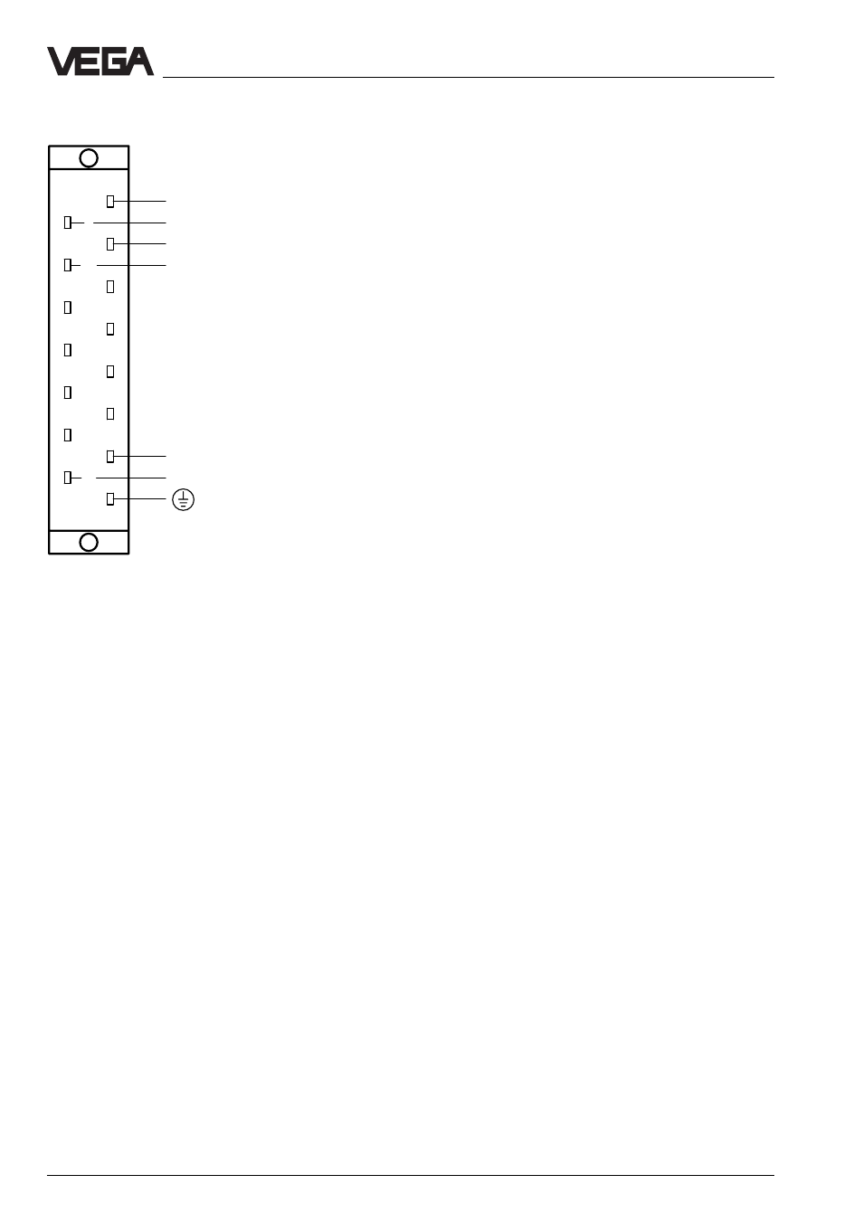
Electrical connection
4
6
8
10
12
14
16
18
20
22
24
26
28
30
32
VEGASTAB 593
Supply voltage (note data of
the type plate or position of the
voltage changeover switch)
Connections 12␣ …␣ 24 not co-
ordinated
Multiple plug acc. to DIN 41␣ 612, series H, 15-pole
Vout (+)
Vout (+)
GND (-)
GND (-)