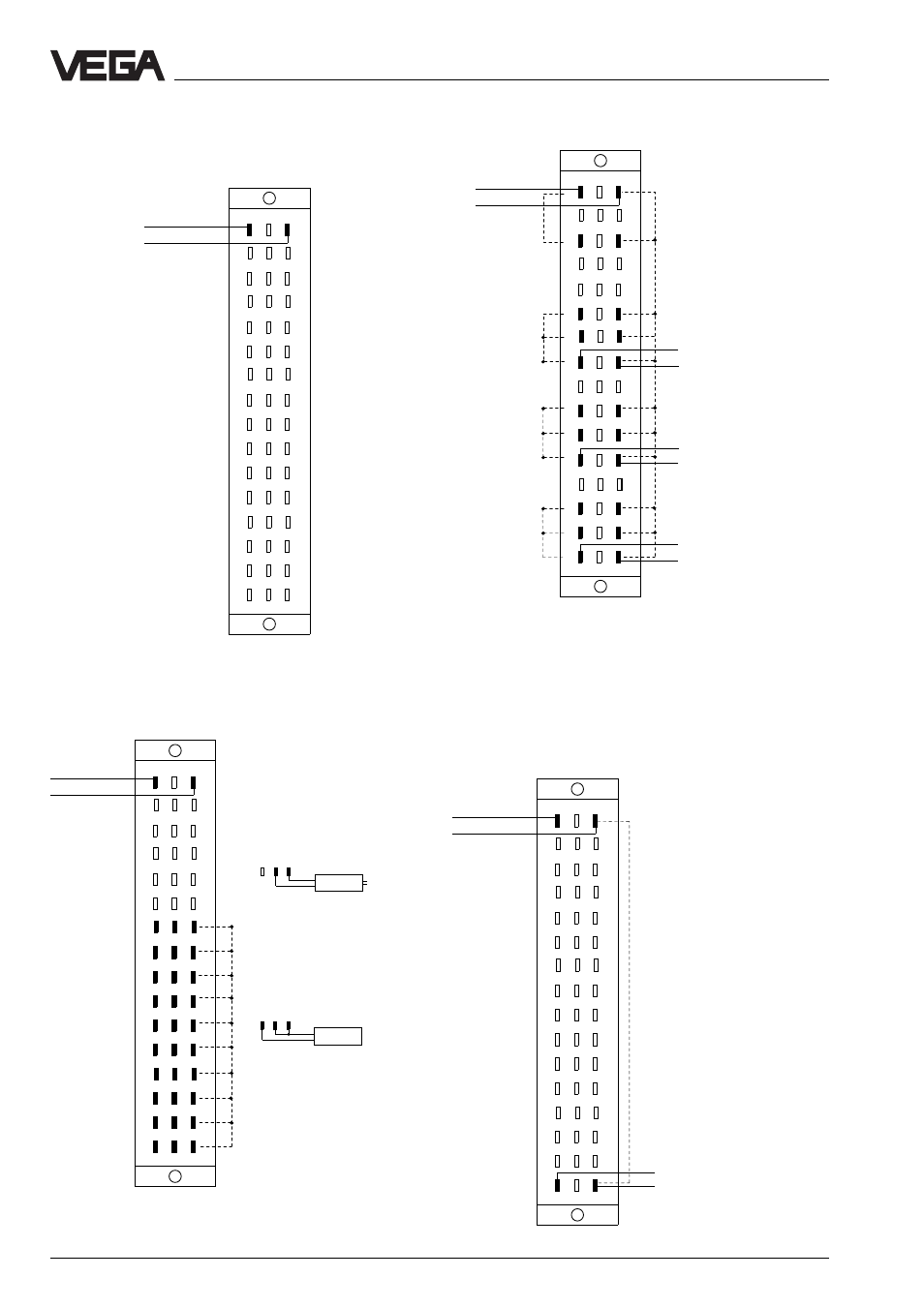
4 connection plans, Ad-card, Cpu-card – VEGA VEGALOG 571 User Manual
Page 30: Ea-card ev-card, Electrical connection
30
VEGALOG 571
AD-card
2
6
12
20
28
24
22
10
16
18
30
32
d b z
L (+)
N (-)
14
26
8
4
+
-
Supply
voltage
max. 2␣ x␣ 15 indicating
instruments VEGADIS
174
The other contacts (d4
to z32) are not co-
ordinated
3.4 Connection plans
CPU-card
Electrical connection
EA-card
EV-card
2
6
12
20
28
24
22
10
16
18
30
32
d b z
L (+)
N (-)
14
26
8
4
Supply
voltage
The other contacts (d4
to z32) are not co-
ordinated
2
6
12
20
28
24
22
10
16
18
30
32
d b z
L (+)
N (-)
14
26
8
4
+
+
-
+
+
-
+
+
-
+
+
-
+
+
-
+
+
-
+
+
-
+
+
-
+
+
-
+
+
-
2
6
12
20
28
24
22
10
16
18
30
32
d b z
L (+)
N (-)
14
26
8
4
-
-
+
-
+
+
Supply
voltage
Supply
voltage
max. 5 ultrasonic, radar
sensors or pressure
transmitters
max. 5 ultrasonic, radar
sensors or pressure
transmitters
max. 5 ultrasonic, radar
sensors or pressure
transmitters
Note:
All 10 sensor inputs
(z14␣ …␣ z32) are connected
(broken line).
Note:
- The connections d12␣ …␣ d16, d20␣ …␣ d24 as well as d28␣ …␣ d32
are connected.
- The connections z12 … z16, z20␣ …␣ z24 and z28␣ …␣ z32 are on
the same minus potential (broken line).
Each sensor input can be
switched passively as well as
actively.
Connection of an active
sensor (sensor delivers
current):
Connection of a passive
sensor (EA-card powers
sensor):
d b z
d b z
Sensor
U
B
Sensor
Sensor 1
Sensor 2
Sensor 3
Sensor 4
Sensor 5
Sensor 6
Sensor 7
Sensor 8
Sensor 9
Sensor 10
Note:
The connection z32 is on the
minus potential (broken line).