VEGA Conductive electrodes User Manual
Page 33
Conductive measuring system
33
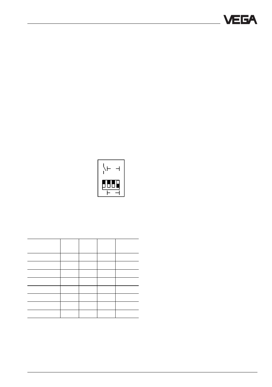
DIL-switch block
A DIL-switch block with 4 switches is located
laterally on top (covered in mounted
condition). The individual switches are
coordinated as follows:
1 A/B-mode
A - Max. detection or overfill protection
B - Min. detection or dry run protection
2 Integration time 2 s
3 Integration time 6 s
4 Integration time 12 s
With switch 1 the mode (A - overfill protection
or B - dry run protection) can be adjusted.
In the example in the figure mode A (max.
detection or overfill protection) is selected
(switch 1). The integration time is adjusted to
8 seconds (switch 2, 3 and 4).
1 A/B-mode
2 Integration time +2 s
3 Integration time +6 s
4 Integration time +12 s
With switches 2, 3 and 4 the integration time
can be appropriately adjusted. The times of
the activated timer sum up. The adjusted time
is valid for the switch on and off delay.
Switch
1
2
3
4
Time
2 s
6 s
12 s
0,2 s
A/B
off
off
off
2 s
A/B
on
off
off
6 s
A/B
off
on
off
8 s
A/B
on
on
off
12 s
A/B
off
off
on
14 s
A/B
on
off
on
18 s
A/B
off
on
on
20 s
A/B
on
on
on
Failure adjustment, bridge (5)
For monitoring of the electrodes and their
circuit a resistor of 220 kOhm must be
mounted between connection 1 and
connection 2 in the connection housing of the
electrode, i.e. with single point control
measuring and mass electrode are
monitored and with double point control max.
and mass electrode.
For electrodes without 220 kOhm resistor a
bridge (5) must be provided on the signal
conditioning instrument between terminals 3
and 4.
Note
With this bridge, the line monitoring and the
fault signal are inactive.
If a measuring system is used as part of an
overfill protection, the bridge must not be
closed.
On Ex-electrodes of VEGA this resistor is
already available as factory setting.
Selection of mode
Mode A or B can be adjusted by means of
the selection switch (13).
Mode A
preferably as overflow protection
compulsorily as overfill protection
means with covered max.-electrode
- relay deenergizes, connection 12 - 13 is
connected through relay
- transistor output blocks
- LED output extinguishes
means with uncovered max.-electrode (level
detection) or min.-electrode (pump control)
- relay energizes, connection 12 - 14 is
connected through relay
- transistor output is conductive
- LED output lights
1
2
3
4
12
6
2
A
B
off
sec t
Set-up