3 electrical connection, 1 vegator 256c, 2 vegator 532 ex – VEGA Conductive electrodes User Manual
Page 23: Pump control (min-max-control), Level detection, Double level detection, Electrical connection, Conductive measuring system 23
Conductive measuring system
23
1
2
3
1
2
3
2
20
28
24
22
16
18
32
d b z
+
-
+
-
+
-
L (+)
N (-)
6
10
12
30
Electrical connection
1 2
;;;;;
0
10
8
7
6
5
4
N
L1
3
2
1
max.
min.
R
2
00
...2
50VAC
3
VA
Re
lais: m
ax
2
50V
,5
A
,7
50VA
powe
r s
upply
1
2
3
1
2
3
0
10
8
7
6
5
4
N
L1
3
2
1
max.
min.
R
200...250VAC 3VA
Re
lais: m
ax
2
50V
,5
A
,7
50VA
power supply
Power
supply
Relay output 1
Relay output 2
Transistor output 1
Transistor output 2
Meas. data input 2
(channel 2)
Electrode
e.g. type EL 3
Electrode
e.g. type EL 3
Electrode
e.g. type EL 1
Mass
Mass
Max
Min
Mass
Max
Min
Meas. data input 1
(channel 1)
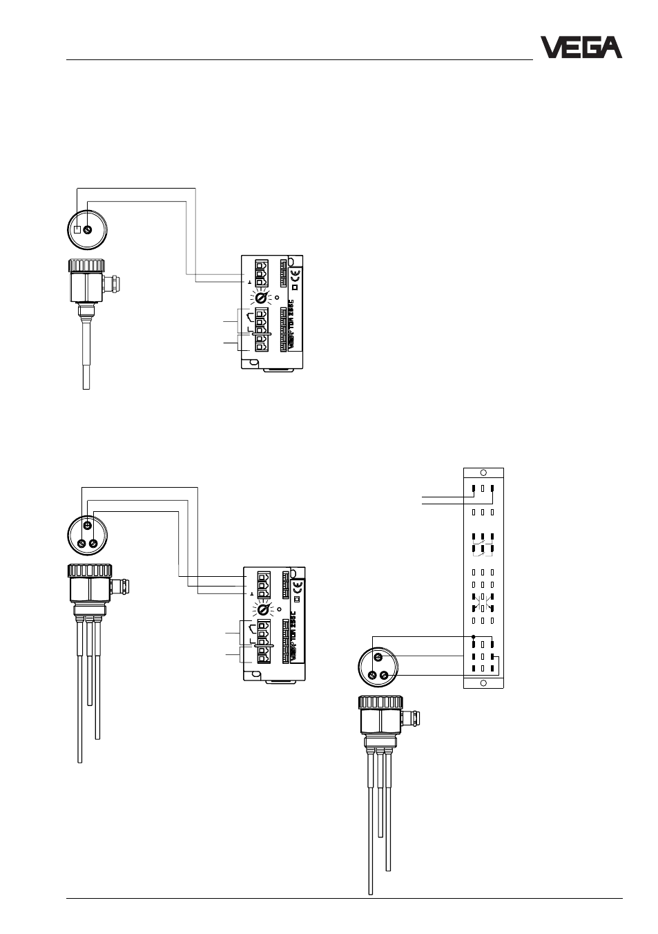
Pump control
(Min-Max-control)
3 Electrical connection
3.1 VEGATOR 256C
Level detection
Note
Multiple rod electrodes which are connected
to several signal conditioning instruments or
a multiple channel instrument, require an
earth rod to avoid influencing among the
signal conditioning instruments.
Connect several VEGATOR 256 C absolutely
identical, i.e. the first supply line to all
terminals no. 7 and the second supply line to
all terminals no. 8. An interchanging of no. 7
and no. 8 or the connection of different
phases is not permitted.
3.2 VEGATOR 532 Ex
To avoid interferences by capacitive
couplings, use from a line length of 50 m an
own cable for each signal conditioning
instrument VEGATOR 532 Ex or for each
channel.
When you want to use a commen cable, note
that the lines of the max. and min. signal are
screened. Connect the screens to mass.
Double level detection
Power supply
Relay output
Power supply
Relay output