2 mounting instructions, 1 conductive electrodes – VEGA Conductive electrodes User Manual
Page 19
Conductive measuring system
19
Mounting instructions
2 Mounting instructions
2.1 Conductive electrodes
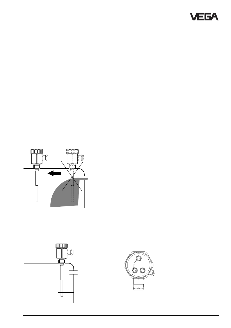
General
When mounting the electrodes it should be
noted that the rod or cable electrodes do not
touch the vessel wall.
Lateral load
Note that the electrode is not subjected to
strong lateral forces.
Mount the electrode on a position in the
vessel where no interferences such as e.g.
by stirrers, vessel openings etc. occur. This
is mainly valid for very long rod and cable
electrodes.
Pressure
In case of gauge or low pressure in the
vessel, the mounting boss must be sealed on
the thread. Use the attached seal ring. Check
if the seal ring is resistant against the
medium.
Note for electrodes with earth rod (e.g. EL 1,
EL 2, EL 8) that the thread of the electrode is
electrically conductive connected with the
vessel to ensure a sufficient ground.
Use conductive seals such as e.g. copper,
lead etc. Isolating measures such as e.g.
covering the thread with Teflon tape or a
paper seal can interrupt the necessary
electrical connection.
In this case connect the earth connection
terminal on the electrode housing via an
external earth cable to the vessel.
Ex-measuring systems
Important instruction for multiple rod or multi-
ple cable electrodes type … Ex, VEGATOR
532 Ex and VEGATOR 631 Ex. To implement
a line monitoring, a resistor of 220 kOhm is
mounted between terminal 1 and terminal 2 in
the connection housing. Please note that in
case you want to adap the rod or cable
electrode by yourself, i.e. shortening so that
L1 or terminal 1 corresponds to the longest
and L2 or terminal 2 to the shortest rod or
cable electrode (see also paragraph "Fault
signal").
Probe with 3 rod or cable
electrodes
If a modification of the installation place
should not be possible for you, it would be
necessary that the rod or cable electrodes
must be stabilized by an isolated holder.
3
2
1