2 vegator 532 ex, Indicating and adjustment elements, Set-up – VEGA Conductive electrodes User Manual
Page 28
28
Conductive measuring system
Set-up
;;;;
;;;;
;;;;
;;;;
;;;;
;;;;
;;;;
;;;;
;;;;
;;;;
;;;;
;;;;
;;;;
;;;;
;;;;
;;;;
;;;;
;;;;
;;;;
;;;;
;;;;
;;;;
;;;;
;;;;
;;;;
;;;;
;;;;
;;;;
;;;;
;;;;
;;;;
;;;;
;;;;
;;;;
;;;;
;;;;
;;;;
;;;;
;;;;
0
10
5
on
0
10
5
2
1
532 Ex
3
4
5
6
7
8
9
10
11
13
16
17
;;
;;
;;
;;;
;;;
18
12
14
B A
B A
1
2
BR2
BR1
15
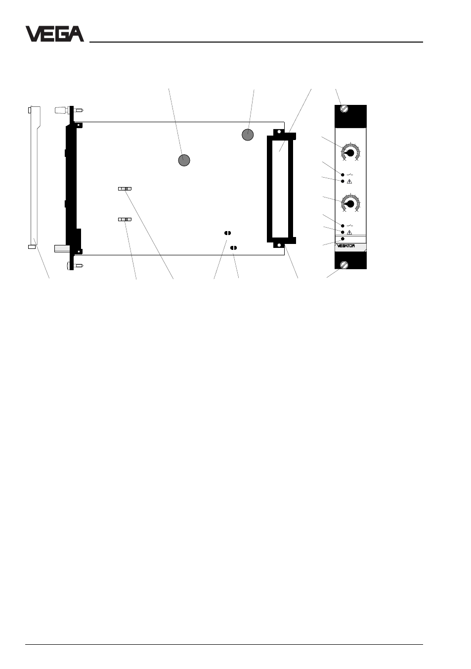
1 Ex-fuse T50 mA / 250 V
2 Mains fuse T 1 A / 250 V
3 Connection plan
4 Lockable screw
5 Potentiometer for switch point
adjustment for channel 1
6 LED output 1
7 LED fault signal channel 1
8 Potentiometer for switch point
adjustment for channel 2
9 LED output 2
10 LED fault signal channel 2
11 LED supply voltage
12 Screw
13 Multiple plug
14 Soldering bridge for fault signal
adjustment channel 1
15 Soldering bridge for fault signal
adjustment channel 2
16 Selection switch mode A/B for
channel 1
17 Selection switch mode A/B for
channel 2
18 Transparent cover
4.2 VEGATOR 532 Ex
Indicating and adjustment elements
Potentiometer
The switch point or the adaption to the
product conductivity can be adjusted via
potentiometer separately for each channel.
Use a small screwdriver to carry out the
adjustments on the potentiometer.
Control lamps
LED in the front plate indicate
operation, switching condition of the relay
outputs and fault signals.
Two yellow LED (6 and 9) for status
indication of the relay or transistor outputs
1 and 2 (LED lights = relay energizes,
transistor conductive, LED extinguished =
relay deenergizes, transistor blocked)
Two red LED (7 and 10) for failure
indication of channel 1 and 2 (LED lights =
channel interferred).
One green LED (11) for indication
operating voltage "on".