3 vegator 631 ex, Indicating and adjustment elements, Set-up – VEGA Conductive electrodes User Manual
Page 32: 32 conductive measuring system
32
Conductive measuring system
4.3 VEGATOR 631 Ex
Set-up
1
2
3
4
5
6
7
8
9
10 11 12 13 14
631Ex
on
0
10
5
5
6
7
8
14
13
12
11
10
9
4
3
2
1
A
B
C
1
2
3
7
8
9
N
L1
-
+
maxim
um
3
4
IP 30
Sensorstromkreis EEx ia IIC
60mA
-
+
o
< x mH
< xxx nF
PTB-Nr.: Ex-96.D.2064
o
o
< x mA
< x,xxV,
o
I
U
L
C
Po < xxmW
max: 36V
5
6
R
nsp.
I
a
: -20É+60¡C
power supply
20É72VDC
1...8 VA
20É250 VAC
L
N
Sensor
1
2
T
er
minal
12 13
out
14
2A
125VA
max.250VAC
9 10
+ -
1
2
3
4
5
6
7
8
9
10
11
12
13
14
15
!
CE
VEGA TOR 631 EX
12
3
4
12
6
2
A
B
off
sec t
minim
um
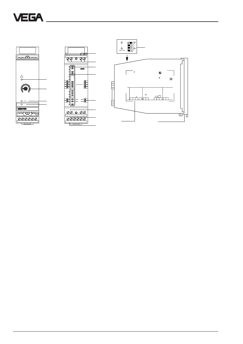
1 LED fault signal
2 Potentiometer for switch point
adjustment
3 LED output
4 LED supply voltage
5 Bridge for failure adjustment
6 Terminal for electrode
7 Function coding Ex-version
8 Instrument coding VEGATOR
631 Ex
9 Sockets for connection bridges
10 Transistor output
11 Relay output
12 Power supply
13 DIL-switch block
14 Type plate
15 Transparent cover
Indicating and adjustment elements
Potentiometer
The switch point or the adaption to the
product conductivity can be adjusted via a
potentiometer.
Use a small screwdriver to carry out
adjustments on the potentiometer.
Control lamps
LED in the front plate indicate
operation, switching condition of the relay
output and fault signal.
One yellow LED (3) for status indication of
the relay or transistor output (LED lights =
relay energized, transistor conductive,
LED extinguished = relay deenergized,
transistor blocks)
One red LED (1) for failure indication (LED
lights = fault signal).
One green LED (4) for indication operating
voltage "on".