Veris Technologies 2000XA Soil EC Mapping System (1997-2008 floppy disk drive 1.76G) - Operating Instructions User Manual
Page 9
Veris Technologies
Pub. #OM 1CM02-1
9
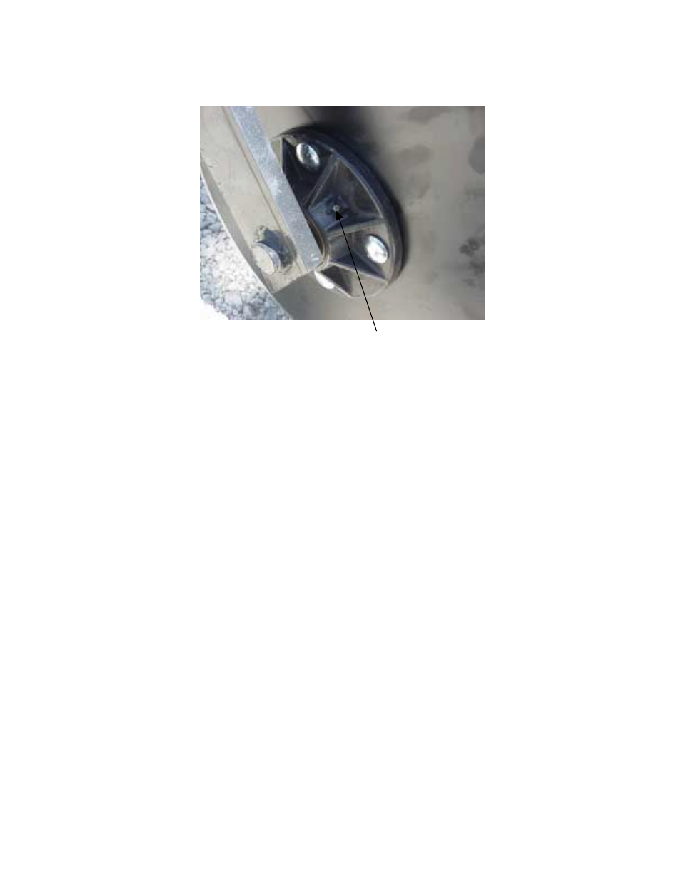
Coulter Hub
Grease zerk
ADJUSTMENTS
Commutators-- The spring-loaded commutators are located in the center of each coulter
electrode hub cap. They are factory preset, and should not need
routine adjustment. If a continuity test shows abnormally high resistance,
the commutators should be checked. This may be performed in the following
manner:
1) Remove the 3/8” allen head set screw.
2) Remove the commutator by turning counter-clockwise.
3) Depress the spring loaded tip on a hard surface to determine if
plunger has adequate tension and can move freely.
4) If the plunger will not move freely, replace, and coat with di-electric
silicone grease.
5) If the commutator appears to be in good working order, reinstall in the
hub, and adjust until it bottoms against the spindle end. Rotate 1/2 turn
backward to allow adequate clearance. Improper adjustment will result in
premature failure (too little tolerance) or poor continuity (too much
tolerance).
6) Reinstall locking set screw and tighten firmly on top of commutator. The
top of the set screw should be even with the face of the hub. If not,
remove and adjust the commutator inward or outward as necessary.
7) Re-test coulter electrode continuity.