Adhesive protection foil – Velleman projects K4040 Assembly instructions User Manual
Page 15
15
Check that the solder side of the PCB, is along the side of the nuts.
Solder a 35 cm length of yellow wire to the 4 Ohm connection (YEL).
Solder a 35 cm length of red wire to the 0 connection (RED).
Fit the unit onto the housing with three black Allen bolts, fix with a shakeproof washer and nut.
Mount the mains voltage connector to the housing using two black Allen bolts.
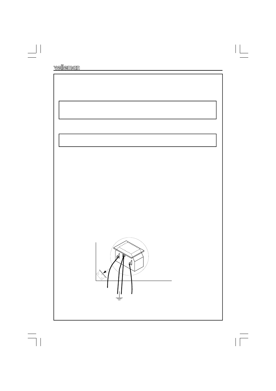
Solder a 12 cm length of blue wire to the N terminal of the mains connector.
Solder a 12 cm length of brown wire to the L terminal of the mains connector.
Solder a 20 cm length of yellow/green earth wire and a 12 cm length to the middle terminal of the
mains connector.
Slide a 1.5 cm length of insulating heat shrink sleeve over each terminal all the way up the con-
nector. This can be shrunken by hot air (e.g. with a hair dryer).
IMPORTANT: Stick a piece of insulating foil on the connector, see figure 4.0. This will later be
used to prevent the connector piercing through the transformer.
Also stick a piece of insulating foil on the inside edge of the cabinet above each place where a
transformer has to be put (see fig. 6).
HINT: In order to tighten the nuts well, immobilise the loudspeaker terminal by inserting a
screwdriver through the hole for the loudspeaker lead.
IMPORTANT: The loudspeaker terminals must NOT touch the metal cabinet anywhere.
ADHESIVE PROTECTION FOIL
Fig. 4.0
Assembly into the unit