Testing – Velleman projects K8006 Assembly instructions User Manual
Page 9
9
CAUTION: MOST PARTS OF THE CIRCUIT CARRY DANGEROUS
VOLTAGES (MAINS) ! OBSERVE ALL SAFETY REQUIREMENTS
THAT MIGHT APPLY !
First, make sure to apply an extra layer of solder on all thinned PCB tracks
because these have to handle high currents.
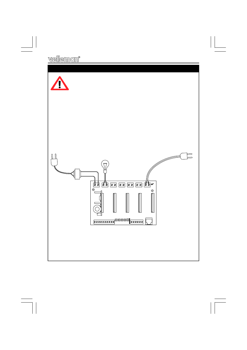
Connect a light bulb rated for the wall outlet voltage (mains) to LOAD 1.
Insert a dimmer module (K8007) or timer module (K8008) into the first slot
(mind the direction, the components must point to the left).
Connect a 24VAC/300mA source (e.g. transformer) to the 24VAC connector.
LD6 will light.
Connect the 110-240V mains to the SUPPLY Neutral and Live connector.
LD7 will light.
Push button SW1. The module will be activated, and the light bulb will light. For
dimmer/timer module operation details, please check their manuals.
All remaining slots must be tested in the same way. Disconnect the mains when
removing modules or wiring.
14. Testing the Unit
24VAC
LOAD1
N
1 C 2 C 3 C
C
VELLEMAN P8006'1
L
SUPPLY
PUSH BUTTON INPUTS
SK1
SK2
SK3
SK4
SK5
10
1
1
1
1
C
3
1
4
5
2
OP
E
N
CO
LL
E
C
T
O
R
IN
P
U
T
S
C
LOAD2
N
LOAD3
N
LOAD4
N
LOAD5
N
N
10
10
10
1 2 3 4 5
DANGER
HIGH
VOLTAGE
24VAC INDICATION
LD6
LD7
24VAC/300mA
TRANSFORMER
D
IM
M
E
R
O
R
T
IM
E
R M
O
DUL
E
WALL OUTLET
WALL OUTLET
4 C 5
SW1 SW2 SW3 SW4 SW5
Testing