Velleman k8006, Circuit bre aker 16a, Final connection – Velleman projects K8006 Assembly instructions User Manual
Page 10
10
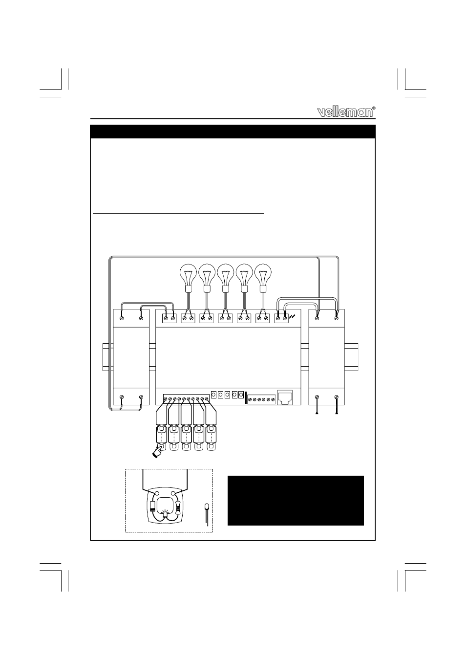
Choose a suitable location for the unit. Probably, the best location is near the
fuse box. An optional enclosure (B8006) is available, for safe installation of the
unit on a DIN rail. Whatever enclosure you use, make sure to provide sufficient
airflow, as the dimmer modules might run hot during use. If you choose the
optional B8006 enclosure, drill a number of ventilation holes in the top and
bottom part of the cover lid.
The drawing below shows a connection example.
Make sure your wiring complies with the local safety requirements.
If doubt, consult a licensed technician !
15. Final Connection
24VAC
LOAD1
N
1 C 2 C 3 C
C
VELLEMAN K8006
L
SUPPLY
C
LOAD2
N
LOAD3
N
LOAD4
N
LOAD5
N
N
1 2 3 4 5
DANGER
HIGH
VOLTAGE
24VAC
PRIM
L
N
L
N
PUSH BUTTONS
AC POWER
C
IRCUIT
BRE
AKER 16A
TR
A
N
S
F
O
R
M
E
R
OP
E
N
C
O
LLE
C
TO
R
IN
P
U
TS
4 C 5
SW1 SW2 SW3 SW4 SW5
2K2
1N4148
C
LED
C
A
A
C
PUSH BUTTON
Final Connection
REMARK: 10 LEDs are provided,
together with diodes and resistors, to
allow push button illumination.
Do not use more than 5 illuminated
push buttons per channel.
Fig. 1.0