MSD 7330 7AL-3 Ignition Control Installation User Manual
Page 9
INSTALLATION INSTRUCTIONS
9
M S D
• W W W . M S D P E R F O R M A N C E . C O M • ( 9 1 5 ) 8 5 7 - 5 2 0 0 • F A X ( 9 1 5 ) 8 5 7 - 3 3 4 4
MULTI-STEP RETARD
There are four retard modules available with the 7AL-3. Each module is activated independently by
supplying 12 volts on the terminal from the corresponding module. The controlling terminals are listed
as RET-1 through RET-4 and are located on the third terminal strip. The modules can be activated in
any order and are cumulative unless deactivated. The maximum amount of retard allowed is a total
of 20° even if the modules add up to more than 20°.
Note: If a Retard function is not going to be used it is recommended to install a "zero" degree module.
See page 12 for more module part numbers.
RETARD WITH THE RPM ACTIVATED SWITCH
The MSD 7AL-3 has both an RPM Activated Switch (RAS) and a Multi-Step Retard. The stages of
retard are activated when the corresponding activation wire isconnected to 12 volts. The RAS can
only activate a circuit by providing a ground path.
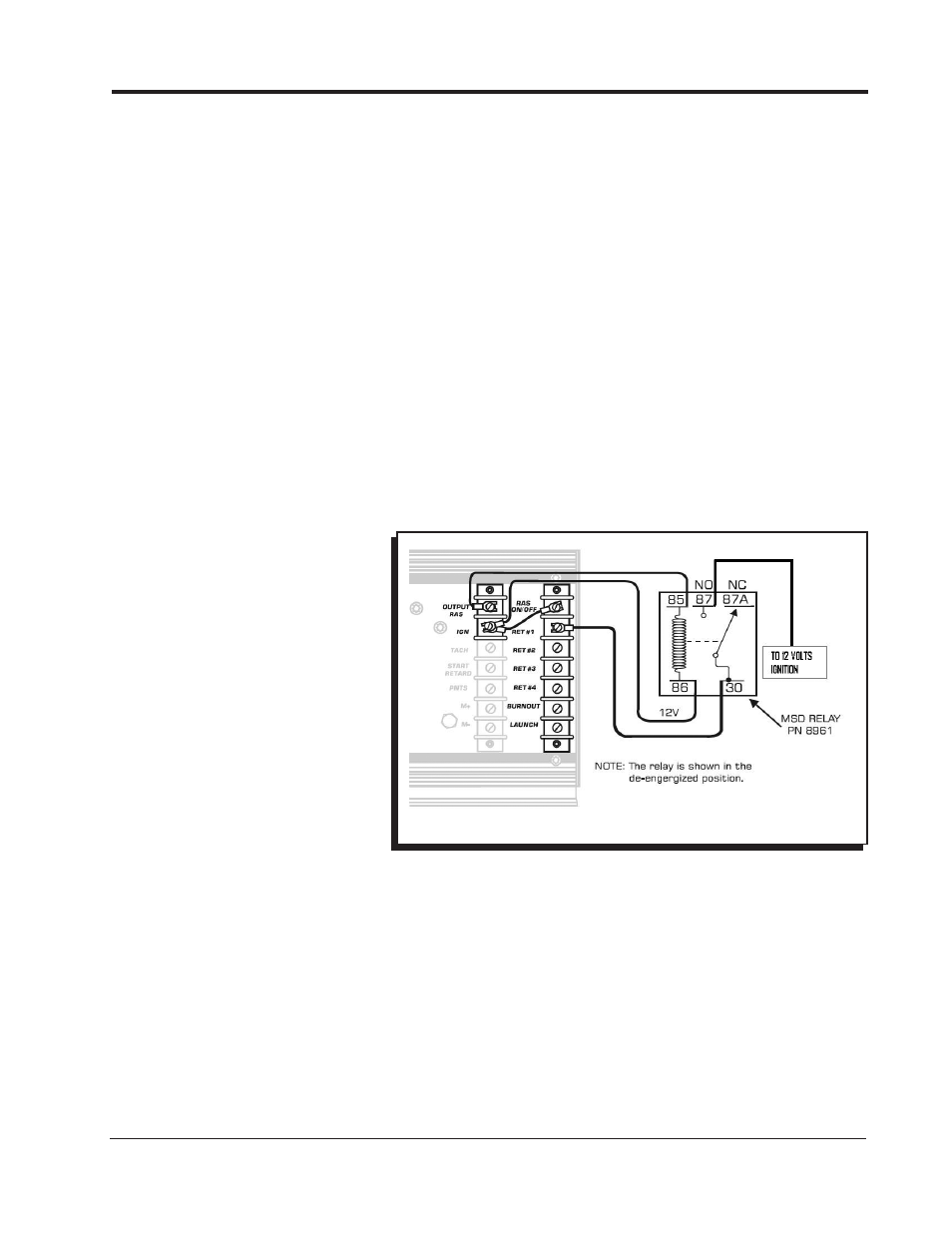
If you want to use the RAS to activate a retard stage of the 7AL-3, an external relay must be used. The
MSD Relay, PN 8961, is supplied in the parts bag with the 7AL-3. Figure 14 shows how to connect
the relay for this application.
Note: Make sure 12 volts is applied to the RAS On/Off terminal.
Figure 15 Activating the RAS in High Gear Only.
For more custom drawings, go to www.msdperformance.com.