Wiring – MSD 8731 2-Step Ford 5.0L Mod Motor 2011 Installation User Manual
Page 2
2
INSTALLATION INSTRUCTIONS
M S D I G N I T I O N
• W W W . M S D I G N I T I O N . C O M • ( 9 1 5 ) 8 5 7 - 5 2 0 0 • FA X ( 9 1 5 ) 8 5 7 - 3 3 4 4
1. Connect the 3-pin harness to the 2-step and connect the Black wire to the good engine or chassis
ground.
2. Disconnect the 2-pin connectors from each of the eight ignition coils.
3. Connect all eight of the 2-pin male connectors from the MSD harness into the factory coil connectors.
4. Plug the 8-pin connector with the single Red wire from the 2-Step to the connector with Black wires.
5. Turn the key to the On position - do NOT start the engine. Look at the LED on the 2-Step:
LED On - This confirms that the wiring is correct and you can move to step 6 (Figure 2).
LED Off - The wiring is different for this application and needs to be changed. Turn the key Off, plug the
8-pin connector with the eight Gray wires into the connector with the single Red wire (Figure 3).
6. Connect the 8-pin harness with the tan wires to the remaining connector on the harness.
7. Connect all eight of the female 2-pin connectors from the MSD harness into the factory coils.
GROUND
ACTIVATION
WIRES
WHITE BLUE
BLUE
ACTIVATES
WITH 12 VOLTS
OR GROUND
TAN
RED
GRAY
BLACK
STEP 1
STEP 3 & 4
STEP 2
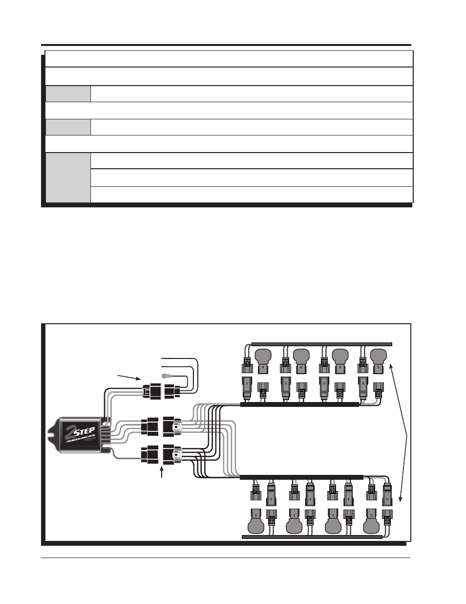
Figure 2 Wiring the 2-Step Launch Control.
WIRING
8-WIRE CONNECTOR
Tan (8)
Signal Connections.
8-WIRE CONNECTOR
Red
12 volt Connection through this single Red wire.
3-WIRE CONNECTOR
Black
Connects to a good engine round or the negative battery terminal.
Blue
Activation Wire. When grounded, the launch feature will be active.
White/Blue Activation Wire. When switched to 12 volts, the launch feature will be active.