MSD 8950 RPM Activated Switch Installation User Manual
Page 2
2
INSTALLATION INSTRUCTIONS
M S D
• W W W . M S D P E R F O R M A N C E . C O M • ( 9 1 5 ) 8 5 7 - 5 2 0 0 • F A X ( 9 1 5 ) 8 5 7 - 3 3 4 4
CYLINDER PROGRAMMING
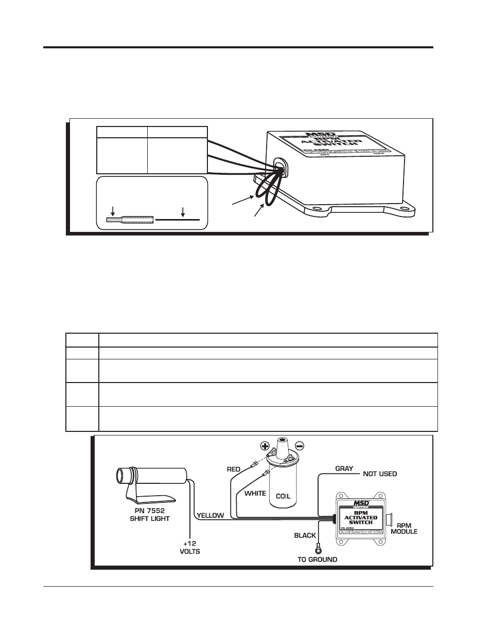
The Switch is programmed for 8-cylinder applications, however it can be used with 4 or 6-cylinder
applications. To program the Switch for different applications, the cylinder select loops must be modified
as shown in Figure 2. After cutting a wire loop, seal the wire end with the supplied heat-shrink caps.
Use a heat gun or other heat source to shrink the cap for a good seal.
Figure 2 Cylinder Select Loops.
Figure 3 Wiring to an Inductive Ignition System.
BLUE
RED
SEAL THE LOOP ENDS
HEAT-SHRINK
CAP
CYLINDER LOOP
CYLINDERS CUT LOOPS
8 NONE
6 RED
4 RED & BLUE
WIRING
Red
Connects to a switched 12 volt source.
Black Connects to ground.
White The rpm input wire. With an MSD Ignition, this connects to the Tach Output terminal.
On inductive ignitions, it connects to the coil negative terminal.
Yellow This is an activation wire and is Normally Open and will switch to ground. It connects
to the ground side of the device you plan to activate.
Gray This is an activation wire and is Normally Closed to ground. It will open the ground
path of a circuit.
MOUNTING
The Switch may be mounted under the hood as long as it is away from direct engine heat sources.
Keep in mind that the rpm modules should be easy to access for changes. The Switch can be mounted
with the double-sided tape or with the four self tapping screws supplied. Use the Switch as a template
and mark the mounting hole locations. Remove the Switch and drill the holes using a 3/16" drill bit
then install the screws.
Note: Inductive ignitions only.