Replacing the distributor gear – MSD 8598 Ford 289_302 Billet Distributor Installation User Manual
Page 7
INSTALLATION INSTRUCTIONS
M S D I G N I T I O N
• w w w . m s d i g n i t i o n . c o m • ( 9 1 5 ) 8 5 7 - 5 2 0 0 • FA X ( 9 1 5 ) 8 5 7 - 3 3 4 4
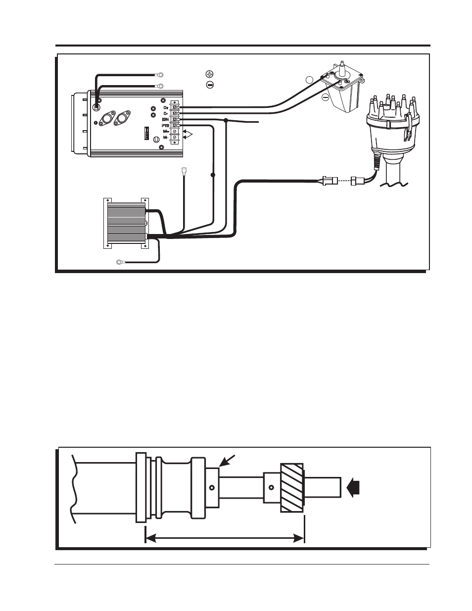
Figure 11 Wiring with an MSD 7-Series Ignition and Timing Control.
T
A
C
H
C+
C-
IGN
PTS
M+
M-
HEAVY RED
TO GROUND
NOT USED
WHITE
WHITE
TIMING
CONTROL
SWITCHED 12 VOLTS
FROM IGNITION KEY
YELLOW
RED
RED
BLACK
NOT
USED
ORANGE
HEAVY BLACK
+
GREEN
VIOLET
+
TO BATTERY
TO BATTERY
Note: MSD 6 and 7 Series Ignitions
share the same color wiring.
rePlacIng The dIsTrIBuTor gear
To replace the distributor gear on the MSD Distributors, the following steps must be followed.
1. Remove the original spiral pin with a punch and press the original gear off the shaft. Press the new
gear onto the shaft and line up the holes for the spiral pin.
Note: The holes may not line up.
2. If the holes line up, measure the distance as shown in the diagram. If the measurement is not correct
or the holes do not line up, a new hole must be drilled. If the measurement is within specifications
and the holes line up, install a new spiral pin.
3. To drill a new hole, turn the gear on the shaft so the gear hole is approximately 90° to the original
shaft hole. Carefully position the gear on the shaft to match the specifications given in the drawing.
Note: Before measuring, push the shaft in to remove all of the end play.
4. When the gear is in the correct position, drill a 0.125” hole through the distributor shaft. Install a
new spiral pin and recheck the measurement.
Note: If the measurement is not within specifications after drilling, a slight correction can be made by
machining the upper face of the thrust collar.
Do not remove more than 0.010” or rotor-to-cap
interference may result.
Figure 12 Replacing the Distributor Gear.
THRUST COLLAR
PRESS FIRMLY TO
TAKE OUT ALL END
PLAY BEFORE
MEASURING.
4.005” MAX.
3.996” MIN.