Installing the distributor – MSD 83506 Ford 351-460 Ready-to-Run Marine Distributor Installation User Manual
Page 5
INSTALLATION INSTRUCTIONS
5
M S D
• W W W . M S D P E R F O R M A N C E . C O M • ( 9 1 5 ) 8 5 7 - 5 2 0 0 • F A X ( 9 1 5 ) 8 5 7 - 3 3 4 4
1. Remove the existing distributor cap without
disconnecting any of the spark plug wires.
2. With the cap off, crank the engine until the
rotor is aimed at a fixed point on the engine or
firewall. Note this position by making a mark
(Figure 8).
3. Place the distributor cap back on and
note which plug wire the rotor is pointing
to. MARK THE SPARK PLUG WIRES and
remove the distributor cap.
4. Disconnect the wiring from the distributor.
5. Loosen the distributor hold down clamp
and slide the clamp out of the way.
6. Lift the distributor out of the engine. Note
that the rotor rotates as you lift the distributor
out. This is due to the helical cut gear and
should be taken into consideration when
installing the new distributor.
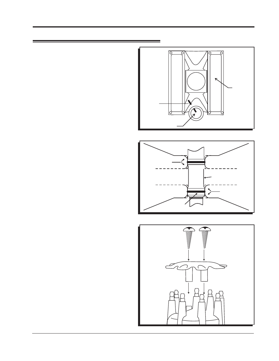
7. Install the gasket and apply a liberal amount
of the supplied lubricant to the distributor
gear. (The supplied O-rings can
only
be used if the Chevrolet block has been
modified as shown in Figure 9.)
8. Install the distributor making sure that the
rotor comes to rest pointing at the fixed mark.
If the distributor will not fully seat with the rotor
pointing to the marked position, you may need
to rotate the oil pump shaft until the rotor lines
up and the distributor fully seats.
9. Position and tighten the hold down clamp onto
the distributor.
10. Install the distributor cap and spark plug wires
one at a time to ensure correct location. A
wire retainer is supplied to secure the wires
in place. Align the mounting bosses and use
the supplied 1.5" self-tapping Phillips screws
to hold the retainer in place (Figure 10).
11. Page 7 shows how to set the rev limiter and
connect the tachometer.
Figure 8 Marking the Rotor Location.
INSTALLING THE DISTRIBUTOR
Figure 9 Modified Chevy Block for use with O-Rings.
Figure 10 Installing the Wire Retainer.
CHAMFER
EDGES
CHAMFER
EDGES
DISTRIBUTOR
HOUSING
O-RINGS
ROTOR
MARK
VALVE
COVER
CARB.