MSD 83921 HVC Professional Racing Distributor for Chevrolet Installation User Manual
Msd dual hall hvc pro-billet distributor, Wiring, Important
The MSD HVC Pro-Billet Distributors are the most advanced racing
distributors available. Take the time to read these instructions thoroughly
before installing the distributor. There are a variety of adjustments that
can be made to improve the performance of your engine and should be
understood prior to running the engine.
Use of a distributor spin machine (or equivalent), is recommended to
take full advantage of the HVC's adjustable features. With a degree
wheel and pointer, you will be able to easily and accurately set the
timing of the secondary pickup.
Wiring
These Distributors have four 2-wire Deutsch connectors that connect
to the ignition control.
Parts Included:
1 - Distributor
1 - Wire Retainer
1 - Coil Wire Retainer
2 - Retainer Screws
MSD Dual Hall HVC Pro-Billet Distributor
Chevrolet - Pn 83921, Ford 351W – Pn 83922
SB Chrysler - Pn 83923, Toyota - Pn 83924,
Chevrolet r07 - Pn 83925, Dodge - Pn 83926
iMPOrTAnT
1 - Gasket (Chevy Only)
2 - O-Rings (Chevy Only)
1 - O-Ring (Ford/Chrysler/Toyota Only)
Parts Required:
Distributor Gear
Harness Assembly, PN 8857
HVC Distributor Reluctor Removal
Tool, PN 83492
Note: The HVC Pro-Billet Distributor is NOT supplied with a gear. See page 2 for gears.
PIckuP ALIGNMENT AND ADjusTMENTs
The HVC Pro-Billet Distributor features a primary and secondary pickup.
These are stacked together with the primary positioned on the bottom. The primary is fixed while the
secondary pickup is adjustable +/- 8°. The pickups are aligned at the factory at 0° advance/retard.
The
position of the secondary pickup will need to be set to your specifications.
When installing the distributor there is an alignment indicator (Figure 3). By aligning the reluctor paddle with
the indicator, the timing will be within approximately +/- 3° of the desired amount. To adjust the secondary
pickup, loosen the two allen head screws on the top pickup. Next, turn the eccentric using an 11/32" wrench
to move the pickup (Figure 3). Secure the screws when the desired timing is reached.
2-PIN CONNECTORS
MALE CONNECTOR
BLACK
Pin 1
Connect to a common ground.
RED
Pin 2
12-volt input. Connect to switched 12 volts.
FEMALE CONNECTOR
BROWN Pin 1
Shielded Ground. Connect to Ground.
WHITE
Pin 2
Trigger Wire. Connect to the points input
(White) wire of the MSD Ignition Control.
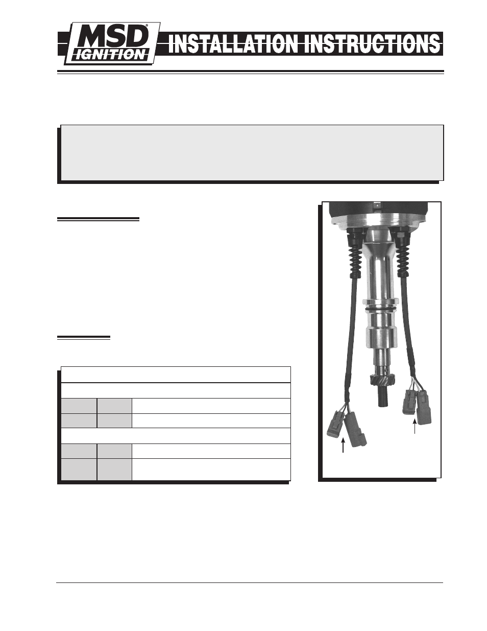
Figure 1 Separate Pickup Connectors.
PRIMARY
NON-ADJUSTABLE
PICKUP
SECONDARY
ADJUSTABLE
PICKUP
M S D I G N I T I O N
• w w w . m s d i g n i t i o n . c o m • ( 9 1 5 ) 8 5 7 - 5 2 0 0 • FA X ( 9 1 5 ) 8 5 7 - 3 3 4 4