MSD 8870 Coil Interface Block,GM Dual Tower Coils Installation User Manual
Page 3
INSTALLATION INSTRUCTIONS
3
M S D
• W W W . M S D P E R F O R M A N C E . C O M • ( 9 1 5 ) 8 5 7 - 5 2 0 0 • F A X ( 9 1 5 ) 8 5 7 - 3 3 4 4
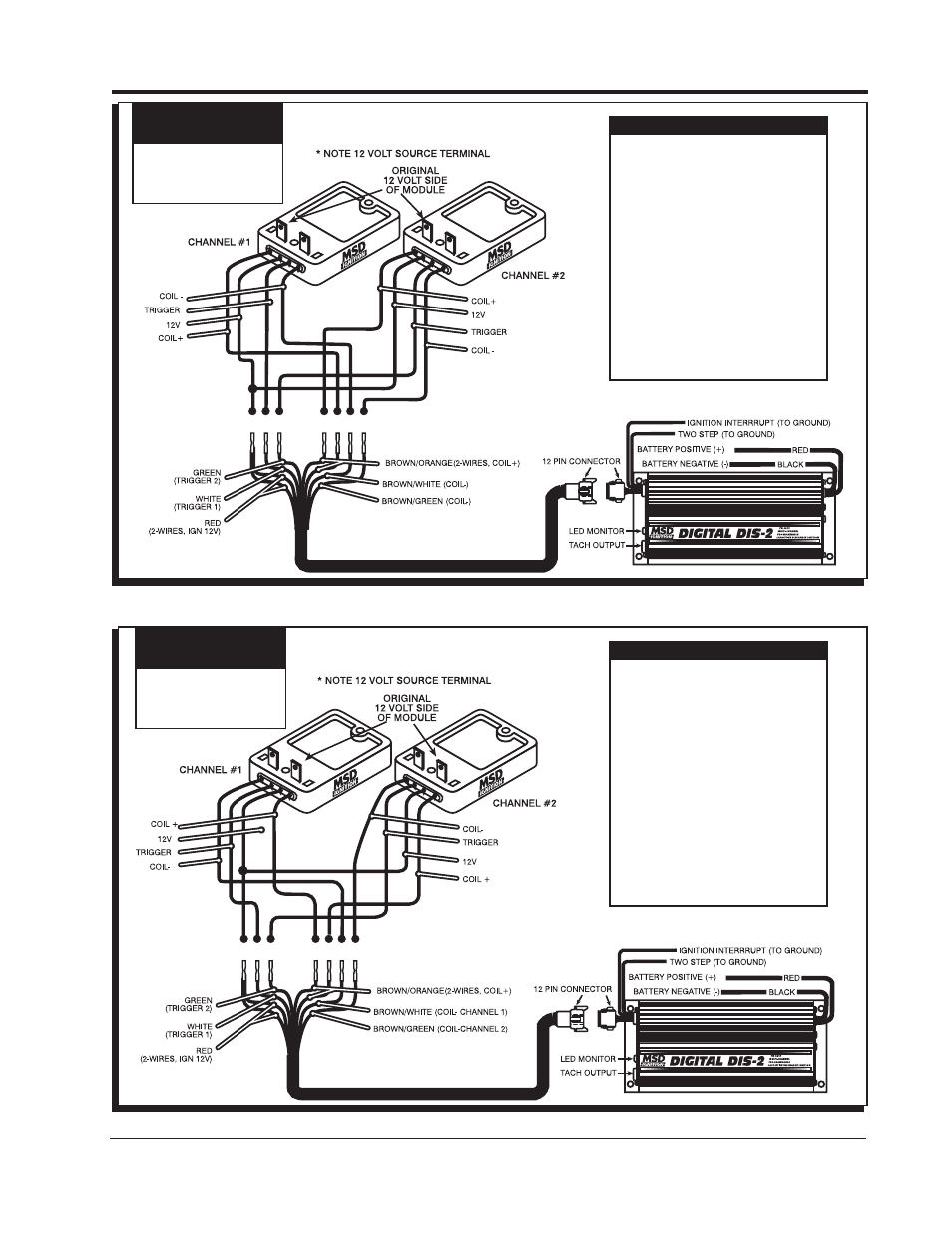
Figure 5 Typical Wiring to a DIS-2 Ignition.
IMPORTANT
WARNING!!
Your car's wiring may be
different, depending on
which module terminal
supplies 12 volts.
WIRE COLOR CODE
Brown/White-Coil (-) Channel 1
Brown/Green-Coil (-) Channel 2
Brown/Yellow-Coil (-) Channel 3
Brown/Violet-Coil (-) Channel 4*
Brown/Orange-Coil(+) High Voltage
White-Trigger Input Channel 1
Green-Trigger Input Channel 2
Yellow-Trigger Input Channel 3*
Violet-Trigger Input Channel 4*
Red-Ignition 12 volts (switched)
Brown-Ignition Interrupt (To Ground)
Blue-Two Step (To Ground)
Red (Heavy)-Battery (+)
Black(Heavy)-Battery(-)
* DIS-4 only
Figure 6 Typical Wiring to a DIS-2 Ignition.
WIRE COLOR CODE
Brown/White-Coil (-) Channel 1
Brown/Green-Coil (-) Channel 2
Brown/Yellow-Coil (-) Channel 3*
Brown/Violet-Coil (-) Channel 4*
Brown/Orange-Coil(+) High Voltage
White-Trigger Input Channel 1
Green-Trigger Input Channel 2
Yellow-Trigger Input Channel 3*
Violet-Trigger Input Channel 4*
Red-Ignition 12 volts (switched)
Brown-Ignition Interrupt (To Ground)
Blue-Two Step (To Ground)
Red (Heavy)-Battery (+)
Black(Heavy)-Battery(-)
* DIS-4 only
Note: Install the gasket between the Interface
and the coil.
Note: Install the gasket between the Interface
and the coil.
IMPORTANT
WARNING!!
Your car's wiring may be
different, depending on
which module terminal
supplies 12 volts.