MSD 89501 RPM Activated Switch, DIS Installation User Manual
Page 2
2
INSTALLATION INSTRUCTIONS
M S D
• W W W . M S D P E R F O R M A N C E . C O M • ( 9 1 5 ) 8 5 7 - 5 2 0 0 • F A X ( 9 1 5 ) 8 5 7 - 3 3 4 4
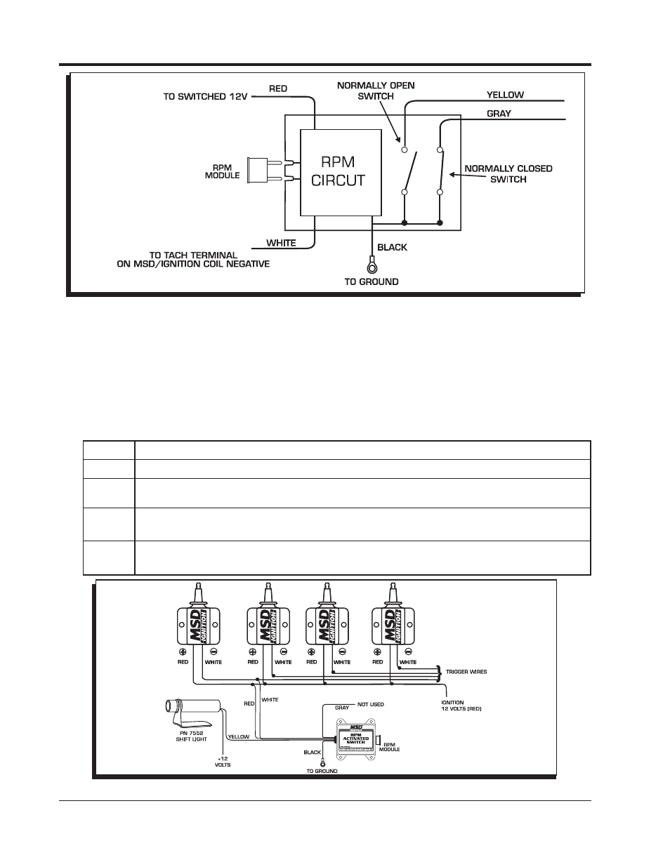
Figure 1 Operation of the RPM Activated Swtich.
WIRING
Red
Connects to a switched 12 volt source.
Black Connects to ground.
White The rpm input wire. With an MSD Ignition, this connects to the Tach Output terminal.
On inductive ignitions, it connects to the coil negative terminal.
Yellow This is an activation wire and is Normally Open and will switch to ground. It connects
to the ground side of the device you plan to activate.
Gray This is an activation wire and is Normally Closed to ground. It will open the ground
path of a circuit.
MOUNTING
The Switch may be mounted under the hood as long as it is away from direct engine heat sources.
Keep in mind that the rpm modules should be easy to access for changes. The Switch can be
mounted with the double-sided tape or with the four self tapping screws supplied. Use the Switch
as a template and mark the mounting hole locations. Remove the Switch and drill the holes using
a 3/16" drill bit then install the screws.
Figure 2 Wiring to a 4-Cylinder, Coil-per-Cylinder Ignition.
- 8428 GM HEI Weight & Spring Kit Installation (2 pages)
- 83811 GM LT-1 5.7L Distributor 95-97 (1 page)
- 8457 Rotor, Includes Base, Fits LP CT Distributors Installation (2 pages)
- 8401 Modified HEI Coil Dust Cover V8 Installation (2 pages)
- 8479 Ford 289_302 Street Pro-Billet Installation (8 pages)
- 8560 Chevy V8 Marine Certified Distributor Installation (8 pages)
- 8918 Tach Signal GMR Pickup Installation (4 pages)
- 8365 GM HEI Billet Distributor Installation (8 pages)
- 8391 Chrysler 331 Ready to Run Distributor Installation (8 pages)
- 2920 Atomic EFI Master Kit (1 page)
- 8467 Racing Rotor MSD Billet Distributors Installation (2 pages)
- 8558 Tall Block Chevy V8 Distributor Installation (4 pages)
- 6011 Ford Modular Ignition Controller for 4.6L_5.4L Installation (8 pages)
- 84333 Black Distributor Cap for Chevy V8, HEI, Retainer Installation (2 pages)
- 7720 Power Grid System - Ignition Control Only Installation (8 pages)
- 5092 DynaForce Starter, Ford BB 351M, 400, 429 Engines Installation (4 pages)
- 6011 Ford Modular Ignition Controller for 4.6L_5.4L Mounting template (1 page)
- Gear Installation on MSD Ford Distributors (1 page)
- 8354 Ford 351W Ready-To-Run Pro-Billet Distributor Installation (8 pages)
- 8580 Ford V8 351C-460 Billet Distributor Installation (8 pages)
- 8996 Multi-Channel Digital Ignition Tester Installation (8 pages)
- 31773 Black Super Conductor Big Block Chevy '75-on, HEI (1 page)
- 8516 AMC Jeep 232-258 4.0L Distributor Installation (8 pages)
- Top Ten Ignition Questions Tech Bulletin (2 pages)
- 8486 Super Tall Block Crab Cap Distributor, Chevy V8 Tech Bulletin (2 pages)
- 8216 GM LS2_LS7 Engine Coil Brackets Installation (2 pages)
- 8960 High Current Relay, DPST Installation (4 pages)
- 85561 Chevy V8 w_Slip Collar Distributor Installation (8 pages)
- 8362 Street Fire Chevrolet V8 GM HEI Distributor Installation (2 pages)
- 6214 Midget DIS-2 Programmable Race Ignition Installation (16 pages)
- 6560 6M-2L Marine Certified Ignition with Rev Limit Installation (12 pages)
- 8725 Electronic Engine Governor Installation (4 pages)
- 8680 Adjustable Timing Control Installation (8 pages)
- 8252 Blaster HVC, Works w_ MSD 6 Series Units Installation (2 pages)
- 8382 Ford 302 Dual Pickup Pro-Billet Distributor Installation (8 pages)
- 8184 2-Pin Deutsch Connector, 12-14 gauge Installation (2 pages)
- 8910 Tach Adapter Installation (2 pages)
- 8912 Tach Adapter for DIS 2 and DIS 4 Ignitions Installation (2 pages)
- 8910_eis Tach Adapter Installation (2 pages)
- 8985 Timing Tapes for Harmonic Balancers Installation (2 pages)
- 8471 Bronze Distributor Gear .500"ID (1 page)
- 8201 Pro Power Coil Installation (2 pages)
- 8595 Ford FE Ready-to-Run Distributor Installation (8 pages)
- 8875 Wiring Harness, GM HEI Installation (2 pages)
- 6010 6LS Ignition Controller for LS1_LS6 (24 tooth crank trigger) Engines Installation (8 pages)