Mounting, Wiring – MSD 6530 Digital Programmable 6AL-2 Installation User Manual
Page 3
INSTALLATION INSTRUCTIONS
3
M S D
• W W W . M S D P E R F O R M A N C E . C O M • ( 9 1 5 ) 8 5 7 - 5 2 0 0 • F A X ( 9 1 5 ) 8 5 7 - 3 3 4 4
MOUNTING
The MSD can be mounted in most positions, except directly upside down (if upside down, moisture
or water cannot escape). It can be mounted in the engine compartment as long as it is away from
direct engine heat sources. It is not recommended to mount the unit in an enclosed area such as
the glovebox.
When you find a suitable location to mount the unit, make sure the wires of the ignition reach their
connections. Hold the Ignition in place and mark the location of the mounting holes. Use a 3/16" drill
bit and drill the holes for the supplied vibration mounts. Install the vibration mounts, then mount the
Ignition.
WIRING
GENERAL WIRING INFORMATION
Wire Length: All of the wires of the MSD Ignition may be shortened as long as quality connectors
are used or soldered in place. To lengthen the wires, use one size bigger gauge wire (12 gauge for
the power leads and 16 gauge for the other wires) with the proper connections. All connections must
be soldered and sealed.
Grounds: A poor ground connection can cause many frustrating problems. When a wire is specified
to go to ground, it should be connected to the battery negative terminal, engine block or chassis.
There should always be a ground strap between the engine and the chassis. Always securely connect
the ground wire to a clean, paint free metal surface.
Ballast Resistor: If your vehicle has a ballast resistor in line with the coil wiring, it is recommended
to bypass it.
ROUTING WIRES
The MSD wires should be routed away from direct heat sources such as exhaust manifolds and
headers and any sharp edges. The trigger wires should be routed separate from the other wires
and spark plug wires. It is best if they are routed along a ground plane such as the block or firewall
which creates an electrical shield. The magnetic pickup wires should always be routed separately
and should be twisted together to help reduce extraneous interference.
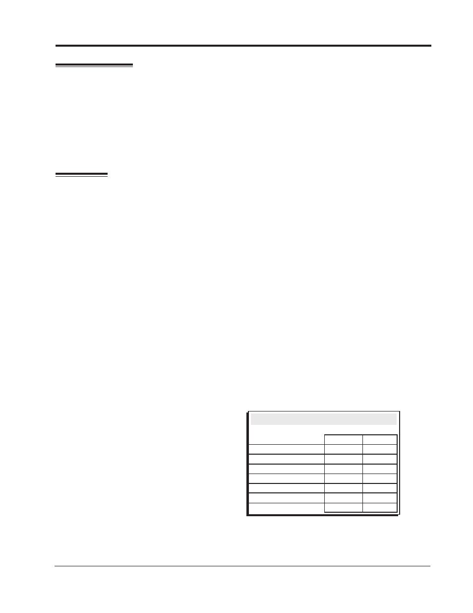
The chart shows the polarity of other common
magnetic pickups. If using a different magnetic
pickup, use the MSD 2-Pin connector, available
as PN 8824, for a direct plug-in installation.
Figure 1 Common Mag Pickup Wires.
Common Mag Pickup Wires
Distributor
Colors
Mag+
Mag-
MSD
Org/Blk
Vio/Blk
MSD Crank Trigger
Violet
Green
Ford
Orange
Violet
Accel
46/48000
Series
Org/Blk
Vio/Blk
Accel
51/61000
Series
Red
Black
Chrysler
Org/Wht
Black
Mallory
Org/Blk
Vio/Blk