MSD 8573 Flathead Ford Ready to Run Distributor for '49-'53 Installation User Manual
Page 7
INSTALLATION INSTRUCTIONS
7
M S D
• W W W . M S D P E R F O R M A N C E . C O M • ( 9 1 5 ) 8 5 7 - 5 2 0 0 • F A X ( 9 1 5 ) 8 5 7 - 3 3 4 4
VACUUM ADVANCE LOCKOUT
If you do not want to use the vacuum advance canister,
MSD has supplied the distributor with a lockout
mechanism. The Lockout bolts in the position of the
vacuum canister and will hold the pickup assembly
firmly in place. The installation is easiest with the
distributor out of the engine.
1. Remove the two Allen head screws that hold the
advance canister (Figure 13).
2. Remove the snap ring that holds the magnetic
pickup assembly in place. This is easy to do with
a set of snap ring pliers by straddling one of the
reluctor paddles.
3. Gently lift up on the mag pickup plate and slide the
vacuum canister out.
4. Install the Lockout Plate in place of the canister.
Install the two retaining screws.
5. Install the supplied screw and washer through the
Lockout and tighten.
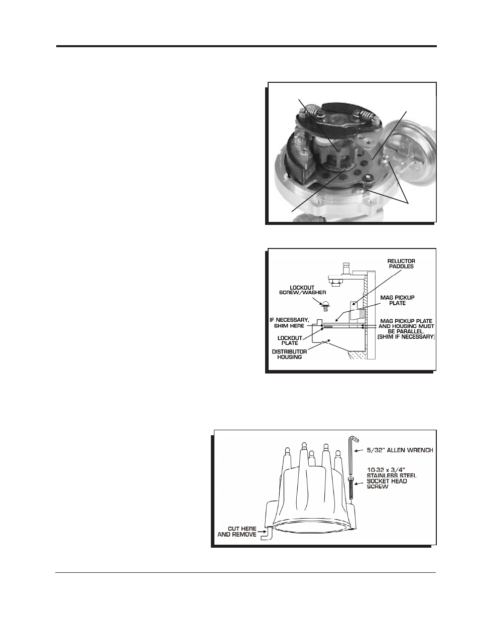
6. It is important to make sure the pickup plate is parallel
with the housing of the distributor (Figure 14). If it is
cocked or slanted, the paddles of the reluctor may
contact the pickup. Check the clearance by rotating
the distributor shaft. If necessary, use the supplied
shims under the Lockout hold-down to correctly
position the pickup plate.
Note: If no shims were required, use one beneath
the washer of the Lock-Out Hold Down Screw.
7. After checking the reluctor to pickup clearance,
tighten the Lockout retaining screws and install the
snap ring.
8. Install the distributor, rotor and cap. Check the timing
when complete.
Note: Do not forget to plug the original vacuum
advance hose.
Figure 14 Checking Installation of the Lockout Plate.
Figure 13 Removing the Vacuum Canister.
RELUCTOR
PADDLES
CANISTER
SCREWS
MAG PICKUP
PLATE
SNAP
RING
Installation Option: This Cap can also
be bolted down to an MSD Pro-Billet or
Billet Distributor base with the supplied
hardware. To accomplish this, the spring
clips must be cut off (Figure 15).
Note: When the cap is bolted down, the
location of the spark plug wires
must be changed.
Figure 15 Optional Installation by Bolting the Cap Down.