MSD 8381 GM LT-1 5.7L 93-94 Distributor Installation User Manual
Page 3
INSTALLATION INSTRUCTIONS
3
M S D
• W W W . M S D P E R F O R M A N C E . C O M • ( 9 1 5 ) 8 5 7 - 5 2 0 0 • F A X ( 9 1 5 ) 8 5 7 - 3 3 4 4
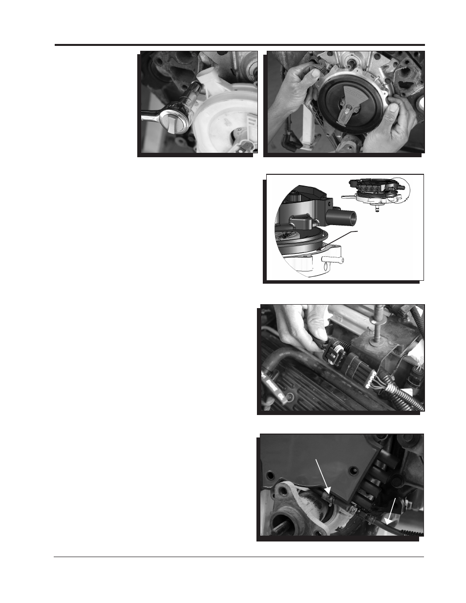
Figure 8 Removing the Distributor.
Figure 9 Installing the New Distributor.
Figure 10 Installing the Seal and Cap.
Figure 11 Distributor Connector.
remove the four
screws that hold
the distributor cap
to the engine and
pull the cap off
(Figure 6). Mark
the location of the
rotor. This will help
ensure the proper
location of the new
distributor (Figure
7).
16. Remove the three
bolts that secure the distributor to the front cover
(Figure 8).
17. Notice the indexing pin on the camshaft (Refer to
Figure 1). Be sure to align the new distributor with the
pin on the cam. The rotor should come to rest in the
same location as it did in Figure 7.
18. Install the new Distributor (Figure 9). Use the supplied
socket head hex screws.
19. Install the square O-ring seal on the billet housing.
Use care not to twist or kink the seal.
20. Install the cap and tighten the five screws evenly.
21. Route the new wiring harness to the top of the intake
and plug in the connector (Figure 11).
VACUUM LINE ROUTING
The PN 8381 Distributor Kit is supplied with a vacuum
line kit that will aid in venting the distributor cap. One
hose assembly connects to a vacuum port on the intake
manifold while the other line connects to the air inlet going
into the throttle body.
1. Connect the long hose assembly to the lower vacuum
inlet of the MSD distributor cap (Figure 12). Use the
supplied clamp to secure the hose.
2. Route the vacuum line around the side of the engine
and up to the intake manifold. Splice into the hose
that connects just over the PCV valve (Figure 13). Also
note the check valve that is in-line. The black side of
the valve must face towards the vacuum source.
3. Connect the smaller vacuum line to the fresh air inlet
port on the top drivers' side of the distributor.
4. Locate the supplied 90° vacuum nipple. Using a 3/16"
drill bit, drill a hole in the air intake duct and install the
nipple (Figure 14). Make sure the barb goes through
and into the duct. Connect the line from the distributor
cap to this inlet. This line completes the fresh air
circulation through the distributor cap (Figure 15).
5. Install the spark plug wires ensuring they are routed
to the correct terminal (Figure 16) and reassemble.
Figure 12 Install the Lower Vacuum Line.
LOWER VACUUM
INLET
TO INTAKE
MANIFOLD
O-RING MUST
SEAT SQUARELY
AGAINST THIS
FLANGE.