MSD 6430 6ALN Ignition Control Installation User Manual
Page 4
INSTALLATION INSTRUCTIONS
M S D I G N I T I O N
• w w w . m s d i g n i t i o n . c o m • ( 9 1 5 ) 8 5 7 - 5 2 0 0 • FA X ( 9 1 5 ) 8 5 7 - 3 3 4 4
MOuNTiNg
The MSD can be mounted in most positions, except directly upside down (if upside down, moisture
or water cannot escape). It can be mounted in the engine compartment as long as it is away from
direct engine heat sources. It is not recommended to mount the unit in an enclosed area such as
the glovebox.
When you find a suitable location to mount the unit, make sure the wires of the ignition reach their
connections. Hold the Ignition in place and mark the location of the mounting holes.
• If you have a 6A Ignition, use an 1/8" drill bit to drill the holes. Use the supplied self tapping screws
to mount the box.
• If you have a 6AL, 6T, 6BTM, 6-Offroad or "N" Series, use a 3/16" drill bit and drill the holes for the
supplied vibration mounts. Install the vibration mounts, then mount the Ignition.
cYLiNDER SELEcT
Note: The 6A, 6T and 6TN do not require any modifications to run on 4 or 6-cylinder even-fire
engines.
The Soft Touch Rev Limiter that is built into the MSD 6AL, 6BTM and 6ALN is programmed for operation
on a 8-cylinder engine. If you are installing one of these units on a 4 or 6-cylinder even-fire engine,
the ignition must be modified. This is easily achieved through the cylinder select device on the side
of the ignition. To program the unit:
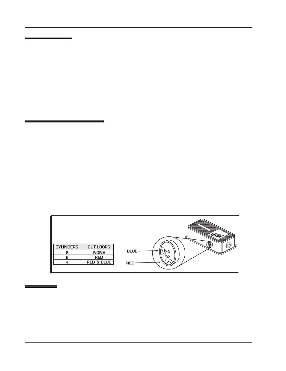
1. Locate and remove the round black cover with a single Phillips screw.
2. There are two wire loops, a Red and Blue loop. Refer to the chart in Figure 2 to determine which
loop to cut for your application.
3. After cutting the loop(s), turn the wire ends away from each other so they cannot come into contact.
Install the cover and screw.
Note: MSD offers Ignition Controls for odd-fire 6-cylinder engines: 6A, PN 6246 and the 6T, PN 6446.
WiRiNg
geNerAL WIrINg INFOrMATION
Wire Length: All of the wires of the MSD Ignition may be shortened as long as quality connectors
are used or soldered in place. To lengthen the wires, use one size bigger gauge wire (10 gauge for
the power leads and 16 gauge for the other wires) with the proper connections. All connections must
be soldered and sealed.
Figure 2 Selecting the number of Cylinders.