Bracket and pickup mount – MSD 8655 Universal Crank Trigger Kit Installation User Manual
Page 2
2
INSTALLATION INSTRUCTIONS
AUTOTRONIC CONTROLS CORPORATION
• 1490 HENRY BRENNAN DR., EL PASO, TEXAS 79936 • (915) 857-5200 • FAX (915) 857-3344
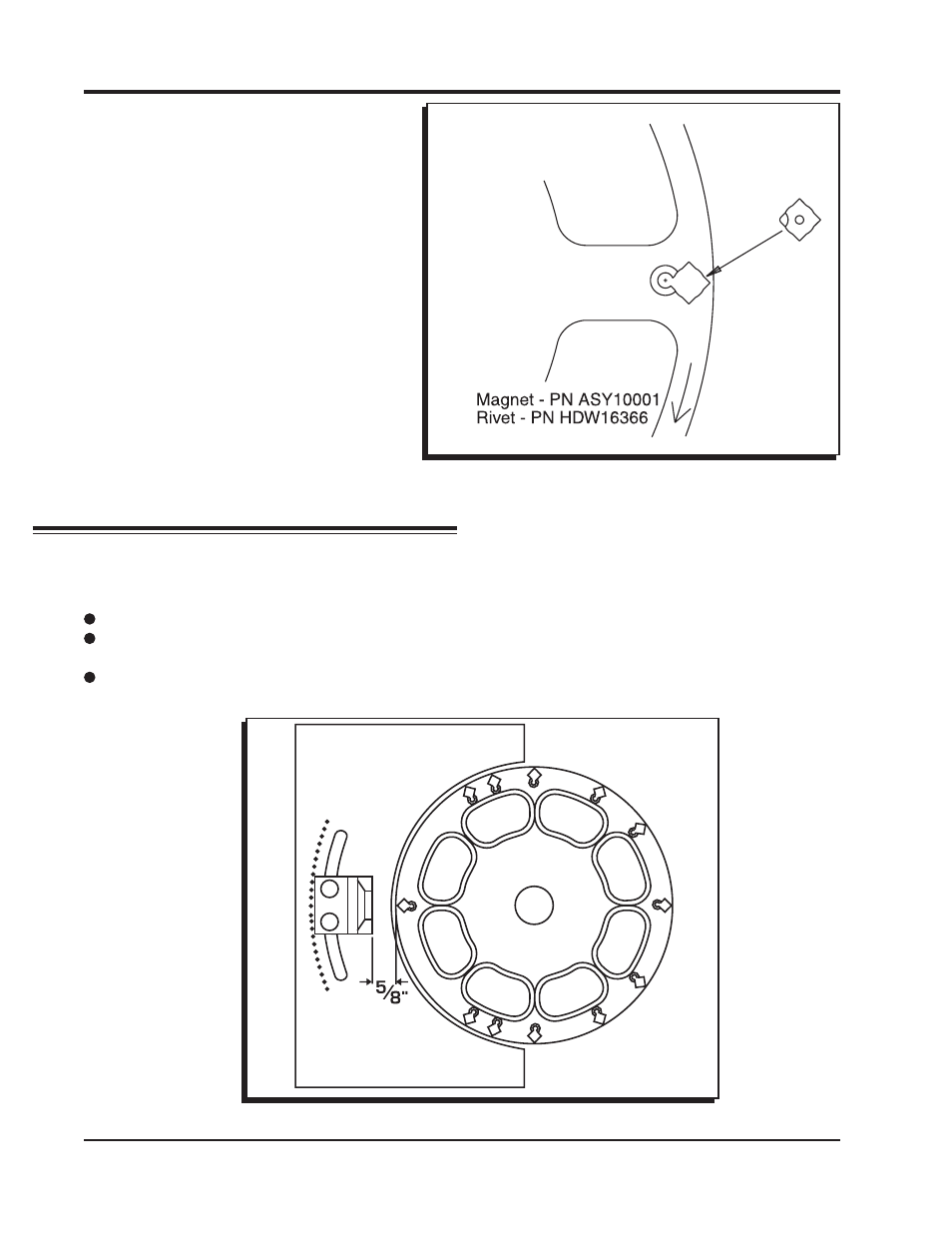
Figure 2 Installing the Magnets.
MAGNET INSTALLATION
The magnets that are supplied are a
matched set and must be installed in one
position to produce the correct trigger
signal.
1. Determine which side of the wheel will
face out. Mark this position.
2. Install the magnet in the wheel with the
hole in the plastic overmolding facing
out from the engine (Figure 2). The
chamfer on the magnet must be
positioned next to the aluminum rivet.
3. Install the rivet. It must be set by using a
press or vice with a set of smooth,
parallel jaws (such as the vice on a
milling machine).
Figure 3 Pickup Bracket Placement.
BRACKET AND PICKUP MOUNT
Once the Trigger Wheel mounting is complete, the brackets need to be created. The mounting
bracket can be cut and machined to meet your requirements. Consider these tips when machining
the bracket:
It is required to have at least two retaining bolts to secure the bracket.
Do not mount the bracket flush to the block. It will be necessary to be able to install the pickup
holder bolt retainer behind the bracket.
The pickup must be spaced 5/8” away from the trigger wheel (Figure 3). This is required so the
air gap between the pickup and trigger wheel will remain constant through its adjustment range.