MSD 5099 DynaForce Starter, AMC (All except 4.0L) Installation User Manual
Msd dynaforce starter, Installation
MSD DynaForce Starter
AMC V8, PN 5099
Parts Included:
1 - Starter
1 - Shim Ring
1 - Outer Shim
WARNING: Before installing the DynaForce Starter disconnect the battery cables. When disconnecting
the battery cables, always remove the Negative (-) cable first and install it last.
IMPORTANT: Proper installation of the DynaForce Starter is important to the overall operation. Correct alignment
of the starter pinion with the ring gear is needed to achieve the best operation and longevity from
your starter. Please read the instructions before attempting the installation.
INSTALLATION
1. Make sure the starter mounting flange on the mid plate is
clean and smooth.
2. Before mounting the starter, measure the distance from the
front of the ring gear (engine side) to the starter mounting
surface. It should be 3/4" (Figure 2).
• If there is not enough clearance, you will need to install
the supplied shim kit by removing the mounting block
(Figure 3). Place the small shim ring in the bearing bore
and install the outer shim on the support housing. Reinstall
the mounting block. This will move the pinion gear into the
starter approximately 0.060".
3. Check that the position of the solenoid is away from direct
heat sources and other components. If there are clearance
problems, the starter housing can be rotated to move the
location of the solenoid. This is done by removing the three
bolts on the mounting block and repositioning the starter
motor (Figure 1).
4. After confirming clearances and positioning. Mount the
starter.
• If there is not enough clearance, you will need to install
the supplied shim kit by removing the mounting block
(Figure 3). Place the small shim ring in the bearing bore
and install the outer shim on the support housing. Reinstall
the mounting block. This will move the pinion gear into the
starter approximately 0.060".
• The gear mesh is not adjustable on this application. Verify
that all parts are correct for the application (flywheel, block
plate, starter) and verify starter is mounted correctly to
engine plate.
5. The switch wire that connects to the solenoid should be at
least 12-gauge (Figure 4). For alternative wiring to incorporate
the factory remote solenoid, See Figure 5.
M S D
• W W W . M S D P E R F O R M A N C E . C O M • ( 9 1 5 ) 8 5 7 - 5 2 0 0 • F A X ( 9 1 5 ) 8 5 7 - 3 3 4 4
ONLINE PRODUCT REGISTRATION: Register your MSD product online and you’ll be entered in our
monthly 8.5mm Super Conductor Spark Plug Wire give-away! Registering your product will help if there
is ever a warranty issue with your product and helps the MSD R&D team create new products that you
ask for! Go to www.msdperformance.com/registration.
Figure 1 Clocking the Starter for Clearance.
CLOCKING
LOCATIONS
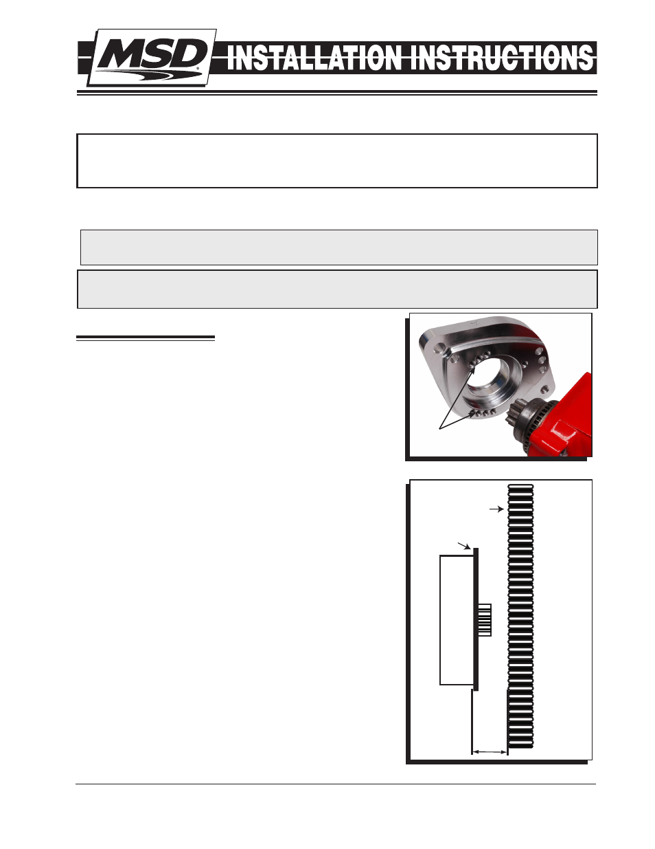
Figure 2 Checking Pinion Clearance.
STARTER
ENGINE BLOCK
TO TRANSMISSION
PLATE
MOUNTING
BLOCK
RING
3/4”
TRANSMISSION
SIDE