MSD 5094 DynaForce Starter, Jeep In-Line 232, 258, 4.0L Installation User Manual
Page 2
2
INSTALLATION INSTRUCTIONS
M S D
• W W W . M S D P E R F O R M A N C E . C O M • ( 9 1 5 ) 8 5 7 - 5 2 0 0 • F A X ( 9 1 5 ) 8 5 7 - 3 3 4 4
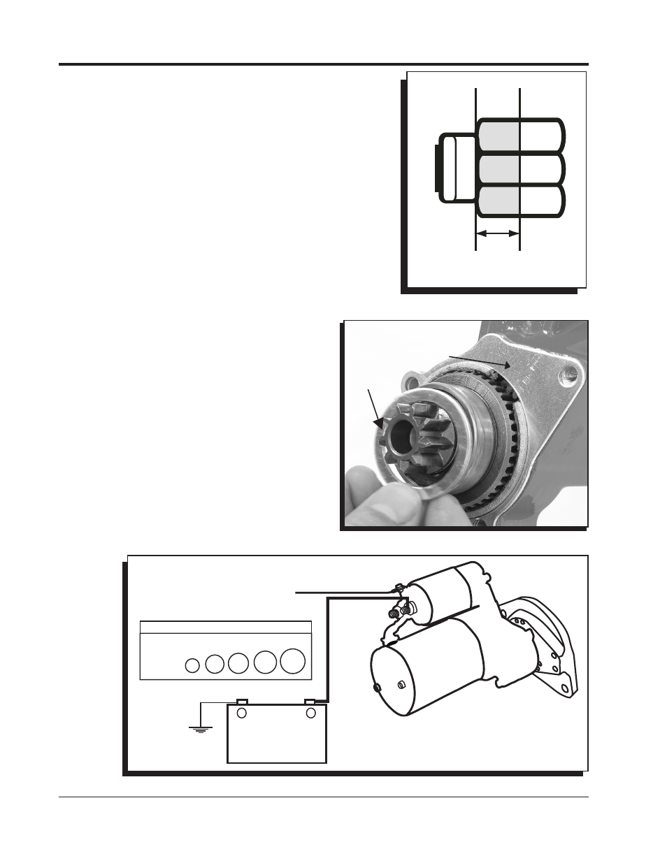
Figure 4 Wiring the DynaForce High Speed Starter.
BATTERY
+
-
LENGTH
3’
5’
7’
10’
+10’
AWG
4
2
1
0
00
CABLE LENGTH VS. GAUGE
12-GAUGE MINIMUM
TO IGNITION
SWITCH
3. After confirming clearances and position of the solenoid, it is
time to check the pinion engagement to the ring gear. This
is done by gently prying out the pinion gear to the ring gear.
The pinion should engage by 1/4" minimum and 3/8" max on
to the ring gear (Figure 2).
• If there is not enough clearance, you will need to install the
supplied shim kit by removing the mounting block (Figure
3). If the pinion gear engages too far onto the ring gear,
there will be issues with disengagement. MSD supplies a
shim ring to move the pinion 0.060". Remove the mounting
block and place the small shim ring in the bearing bore and
install the outer shim on the support housing. Reinstall the
mounting block. This will move the pinion gear into the starter
approximately 0.060".
4. With the starter mounted and gear engagement confirmed,
it is time to connect the wires. The switch wire that connects
to the solenoid should be at least 12-gauge (Figure 4). For
alternative wiring to incorporate the factory remote
solenoid, See Figure 5.
5. Attach the battery cable. The gauge of the battery
cable depends on its length. Using the proper
gauge wire is important to the operation of the
starter. Both the positive and ground wires must
be able to meet the demands of the starter. The
chart in Figure 5 shows the recommended sizes.
Be sure to route the wire away from the exhaust
and moving parts of the engine.
6. Connect the battery terminals and start the engine.
IMPORTANT: Never operate a starter for more than
30 seconds at a time without letting it
cool for at least two minutes.
Figure 2 Pinion Gear Pattern.
THE CORRECT PINION DEPTH
SHOULD MEASURE 1/4” to 3/8”.
Figure 3 Installing the Pinion Shim Spacers.
INSTALL OUTER
SHIM
SHIM
RING