MSD 7720 Power Grid System - Ignition Control Only Installation User Manual
Page 4
4
INSTALLATION INSTRUCTIONS
M S D
• W W W . M S D P E R F O R M A N C E . C O M • ( 9 1 5 ) 8 5 7 - 5 2 0 0 • F A X ( 9 1 5 ) 8 5 7 - 3 3 4 4
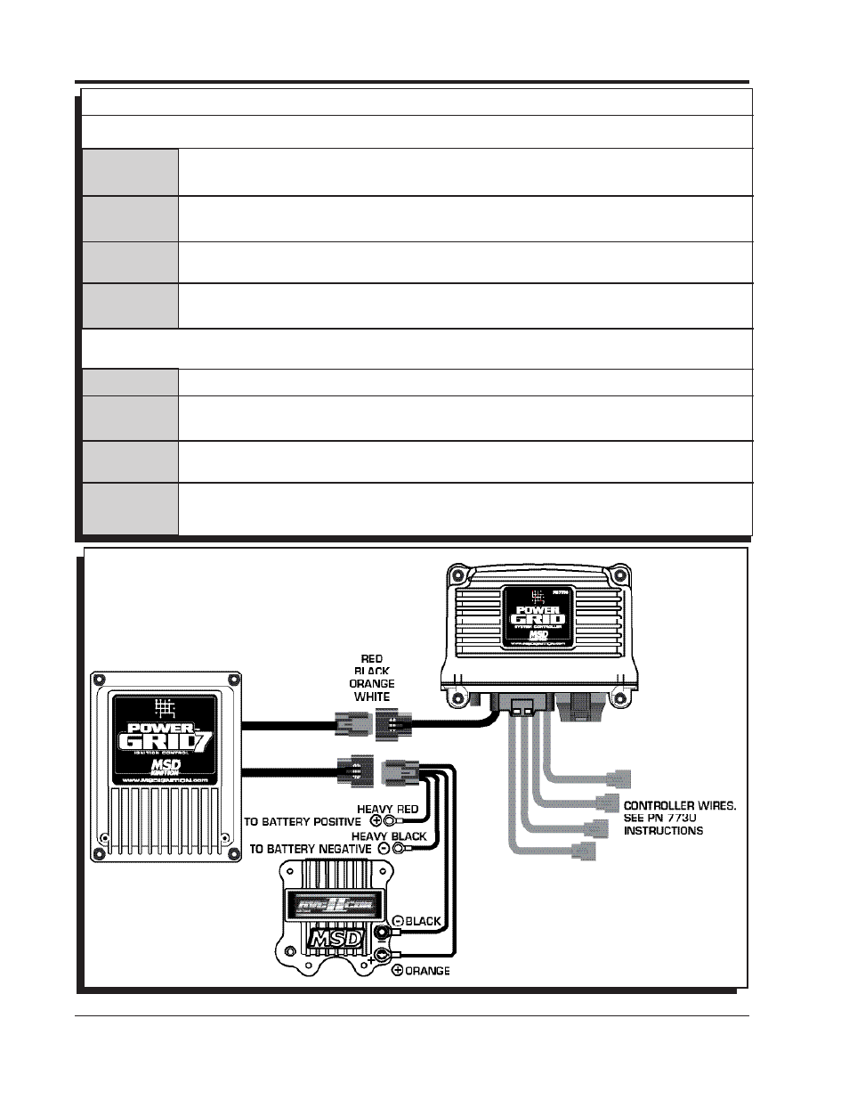
WIRING
Deutsch Male 4-Pin Connector
12ga Red
Battery Positive – This wire connects directly to the battery positive (+) terminal or
to a positive battery junction or the positive side of the starter solenoid.
12ga Black Battery Negative – This wire connects to a good ground, either at the battery negative
(-) terminal or to the engine.
16ga Orange Coil Positive – This wire connects to the positive (+) terminal of the coil. This is the
only wire that makes electrical contact with the coil positive terminal.
16ga Black Coil Negative – This wire connects to the negative (-) terminal of the coil. This is the
only wire that makes electrical contact with the coil negative terminal.
Deutsch Female 4-Pin Connector
18ga Red
Ignition – This wire is switched 12 volts to turn the ignition and modules on and off.
18ga White
Trigger Input – This wire is used to communicate the timing signal from the System
Controller to the ignition.
18ga Black Ground – This wire supplies the ground for the System Controller. This connects
internally with the ground from the heavy Black wire in the first connector.
18ga Orange Battery – This wire supplies power through the Power Grid Ignition to the System
controller.
Figure 1 General Wiring