MSD 6011 Ford Modular Ignition Controller for 4.6L_5.4L Installation User Manual
Page 2
INSTALLATION INSTRUCTIONS
MSD IGNITION
• 1490 HENRY BRENNAN DR., EL PASO, TEXAS 79936 • (915) 857-5200 • FAX (915) 857-3344
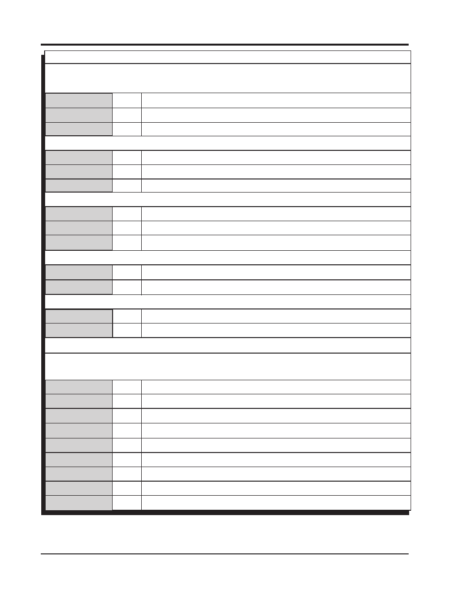
POWEr WirES
rED
12-volt input. Connect to switched 12 volts.
BrOWn/YELLOW
Use only with EFI. Coil input wire.
BLaCK
Ground. Connect eyelet to ground.
LOOSE WirES
YELLOW
Tach Signal. Provides a 12 volt square wave source.
PinK
Step Retard. When 12 volts are applied, the step retard is activated.
BLUE
2-Step. When 12 volts are applied, the RevLaunch rpm value is active.
MaP SEnSOr
BrOWn
Pin-A
Ground
grEEn
Pin-B
Map Signal
OrangE
Pin-C
5-volt supply
CranKShaft SEnSOr
BLaCK
Pin-A
Signal Negative (-)
rED
Pin-B
Signal Positive (+)
CaMShaft SEnSOr
BrOWn
Pin-A
Ground
tan
Pin-B
Signal Wire
COiL COnnECtOrS
rED
Pin-A
* 12-volt supply
viOLEt
Pin-B
* Coil-1 Trigger
rED/grEEn
Pin-B
* Coil-2 Trigger
Lt. BLUE
Pin-B
* Coil-3 Trigger
BrOWn/grEEn
Pin-B
* Coil-4 Trigger
grEEn
Pin-B
* Coil-5 Trigger
WhitE/BLUE
Pin-B
* Coil-6 Trigger
PinK
Pin-B
* Coil-7 Trigger
viOLEt/BLUE
Pin-B
* Coil-8 Trigger
note: For carburetor applications this connector is cut off and the Brown/Yellow is not used. For EFI applications,
this connects to the number one coil connector.
*note: The harness is set up for use on a SOHC engine. DOHC engines use coils with reversed polarity. In these
applications, the location of two coil wires needs to be swapped in each connector.