American Magnetics 175 Industrial Level Transmitter (CE-Marked) User Manual
Page 14
14 of 18
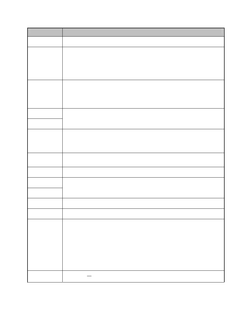
Menu Item Descriptions
F
UNCTION
D
ESCRIPTION
Units
This is used to select the measurement units shown on the display.
These units are used during the calibration process.
Hi Cal
This is used to set the high calibration point on the probe. This can
either be the highest liquid level on the probe (preferably), or the
highest achievable level during calibration. The order in which the “Lo
Cal” and “Hi Cal” are set is not important, only that the “Lo
Cal” must be below the “Hi Cal”. A minimum 2% of span change is
required between the two points. These points are independent of the
4mA/20mA points.
Lo Cal
This is used to set the low calibration point on the probe. This can either
be the lowest liquid level on the probe (preferably), or the lowest
achievable level during calibration. The order in which the “Lo Cal”
and “Hi Cal” are set is not important, only that the “Lo Cal” is
below the “Hi Cal”. A minimum 2% of span change is required between
the two points. These points are independent of the 4mA & 20mA points.
20 mA Pt
4 mA Pt
These are the levels in the vessel corresponding to the 4mA and 20mA
outputs. They will usually be different from the “Lo Cal” & “Hi Cal” points.
Prox Cal
After the unit has been calibrated for a particular fluid, “ProxCal” will
allow you to adjust the calibration for a different fluid without changing the
level in the vessel. The “Hi Cal” and “Lo Cal” points must not be changed
when using ProxCal. If you recalibrate the transmitter in the new fluid,
change the ProxCal value back to 100.0
Damping
This is an exponential decay filter used to slowdown the output response
time of the transmitter. This, in effect, stabilizes the output and display in
a turbulent vessel.
Error
This determines the value of the output current upon detection of a fault
condition (capacitance out of range, dead oscillator, loss of signal, etc.).
Trim 20
Trim 4
This allows for an adjustment of the D/A converter for the 4-20mA output.
This insures that the unit display matches the actual 4-20mA signal.
(measured with a mA meter).
Poll Adr
Not used.
Loop Cur
This feature allows the user to set the transmitter output to a fixed value
from 3.6 to 22mA. This allows the user to test other devices in the loop.
RNG:CNTS
RNG displays the calibration range (0 to 7). The transmitter automatically selects the
Range value during the calibration process.
0 = 0 to 781pF 3 = 0 to 6,250pF 6 = 0 to 50,000pF
1 = 0 to 1,562pF 4 = 0 to 12,500pF 7 = 0 to 100,000pF
2 = 0 to 3,125pF 5 = 0 to 25,000pF
CNTS displays the digital counts that correspond to the capacitance being measured
within the Range selected (Troubleshooting tool). 0 to 65,535 counts within each
range.
Clr Mem?
This erases all values in the transmitter, and resets them back to factory default
values. Recalibration is required if “Clr Mem?” is used.