English motherboard layout, Fatal1ty x79 professional series motherboard, Intel x79 – ASRock Fatal1ty X79 Professional User Manual
Page 4: Pled1, Speaker1 hdled reset pled pwrbtn panel1, Cir1, X79 professional fatal1ty
4
Fatal1ty X79 Professional Series Motherboard
English
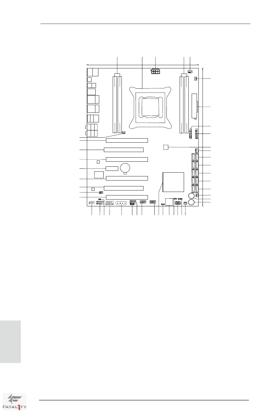
Motherboard Layout
1
2 x 240-pin DDR3 DIMM Slots
24
Dr. Debug
(DDR3_A1, DDR3_B1, Black)
25
Clear CMOS Jumper (CLRCMOS1)
2
2011-Pin CPU Socket
26
Intel X79 Chipset
3
ATX 12V Power Connector (ATX12V1)
27
USB 2.0 Header (USB_10_11, Black)
4
2 x 240-pin DDR3 DIMM Slots
28
USB 2.0 Header (USB_8_9, Black)
(DDR3_D1, DDR3_C1, Black)
29
USB 2.0 Header (USB_6_7, Black)
5
CPU Fan Connector (CPU_FAN1)
30
Consumer Infrared Module Header
6
CPU Fan Connector (CPU_FAN2)
(CIR1, Gray)
7
ATX Power Connector (ATXPWR1)
31
SLI / XFIRE Power Connector
8
USB 3.0 Header (USB3_5_6, Black)
32
COM Port Header (COM1)
9
USB 3.0 Header (USB3_7_8, Black)
33
HDMI_SPDIF Header
10
SPI Flash Memory (64Mb)
(HDMI_SPDIF1, Black)
11
Chassis Fan Connector (CHA_FAN1)
34
Front Panel IEEE 1394 Header
12
SATA2 Connectors (SATA2_2_3, Black)
(FRONT_1394, Black)
13
SATA2 Connectors (SATA2_0_1, Black)
35
Front Panel Audio Header
14
SATA3 Connectors (SATA3_0_1, Red)
(HD_AUDIO1, Black)
15
SATA3 Connectors (SATA3_M0_M1, Red)
36
PCI Express 3.0 x16 Slot (PCIE5, Red)
16
SATA3 Connectors (SATA3_M2_M3, Red)
37
Infrared Module Header (IR1)
17
Chassis Fan Connector (CHA_FAN3)
38
PCI Slot (PCI2, Black)
18
Power Switch (PWRBTN)
39
PCI Express 3.0 x16 Slot (PCIE4, Red)
19
Reset Switch (RSTBTN)
40
PCI Express 2.0 x1 Slot (PCIE3, Black)
20
Chassis Fan Connector (CHA_FAN2)
41
PCI Express 3.0 x16 Slot (PCIE2, Red)
21
Chassis Speaker Header (SPEAKER1, Black) 42
PCI Slot (PCI1, Black)
22
System Panel Header (PANEL1, Black)
43
PCI Express 3.0 x16 Slot (PCIE1, Red)
23
Power LED Header (PLED1)
44
Power Fan Connector (PWR_FAN1)
D
D
R
3
_
D
1
(
6
4
b
it
, 2
4
0
-p
in
m
o
d
u
le
)
D
D
R
3
_
C
1
(
6
4
b
it
, 2
4
0
-p
in
m
o
d
u
le
)
ATX12V1
D
D
R
3
_
A
1
(
6
4
b
it
, 2
4
0
-p
in
m
o
d
u
le
)
D
D
R
3
_
B
1
(
6
4
b
it
, 2
4
0
-p
in
m
o
d
u
le
)
A
T
X
P
W
R
1
24.4cm (9.6 in)
3
0
.5
c
m (
1
2
.0
in
)
Intel
X79
Dr.
Debug
RSTBTN1
PWRBTN1
S
A
T
A
3
_
M
2
_
M
3
S
A
T
A
3
_
M
0
_
M
1
S
A
T
A
2
_
2
_
3
S
A
T
A
2
_
0
_
1
S
A
T
A
3
_
0
_
1
64Mb
BIOS
CMOS
Battery
PCIE3
PCIE1
PCIE2
PCIE4
PCIE5
PCI1
PCI2
Super
I/O
SLI/XFIRE_PWR1
AUDIO
CODEC
PLED1
1
1
SPEAKER1
HDLED RESET
PLED PWRBTN
PANEL1
1
CHA_FAN2
C
H
A
_
F
A
N
1
C
P
U
_
F
A
N
2
CPU_FAN1
C
H
A
_
F
A
N
3
U
S
B
2
.0
T
: U
S
B
0
B
: U
S
B
1
P
S
2
K
e
y
b
o
a
rd
Clr
CMOS
Coaxial
SPDIF
Optical
SPDIF
USB 3.0
T: USB1
B: USB2
Top:
IEEE
1394
USB 2.0
T: USB2
B: USB3
Top:
RJ-45
USB 2.0
T: USB4
B: USB5
eS
A
TA
3
US
B
3.
0
T:
USB3
B:
USB4
eS
A
TA
3
T
o
p
:
S
ID
E
S
P
K
C
e
n
te
r:
R
E
A
R
S
P
K
B
o
tt
o
m
:
C
T
R
B
A
S
S
T
o
p
:
L
IN
E
IN
C
e
n
te
r:
F
R
O
N
T
B
o
tt
o
m
:
M
IC
IN
1
HDMI_SPDIF1
1
HD_AUDIO1
FRONT_1394
1
COM1
1
IR1
1
USB_6_7
1
CIR1
1
USB_8_9
1
USB_10_11
1
CLRCMOS1
1
LAN
PHY
1
1
X79 Professional
FATAL1TY
2 oz Copper PCB
X
Fast USB
X
Fast LAN
PCI Express 3.0 Ready
4-Way SLI
USB 3.0
Front USB 3.0
1394a
SATA3 6Gb/s
E
rP
/E
u
P
R
e
a
d
y
R
o
H
S
4
C
h
a
n
n
e
ls
D
D
R
3
D
D
R
3
2
4
0
0
+
Designed in Taipei
U
S
B
3
_
5
_
6
U
S
B
3
_
7
_
8
PWR_FAN1
1
2
3
4
5
6
7
8
9
10
11
12
13
14
15
16
17
18
19
20
21
22
23
24
25
26
27
28
29
30
31
32
33
34
35
36
37
38
39
40
41
42
43
44