Optional installation/connections, Connecting the external time signal – Acroprint ES900 Electronic Time Recorder User Manual
Page 61
ES900 User’s Manual
55
O
PTIONAL
I
NSTALLATION
/C
ONNECTIONS
Connecting the External Time Signal
If external signal(s) are required, the addition of a relay and signal control board (not supplied)
will be necessary.
Please consult your local electrician.
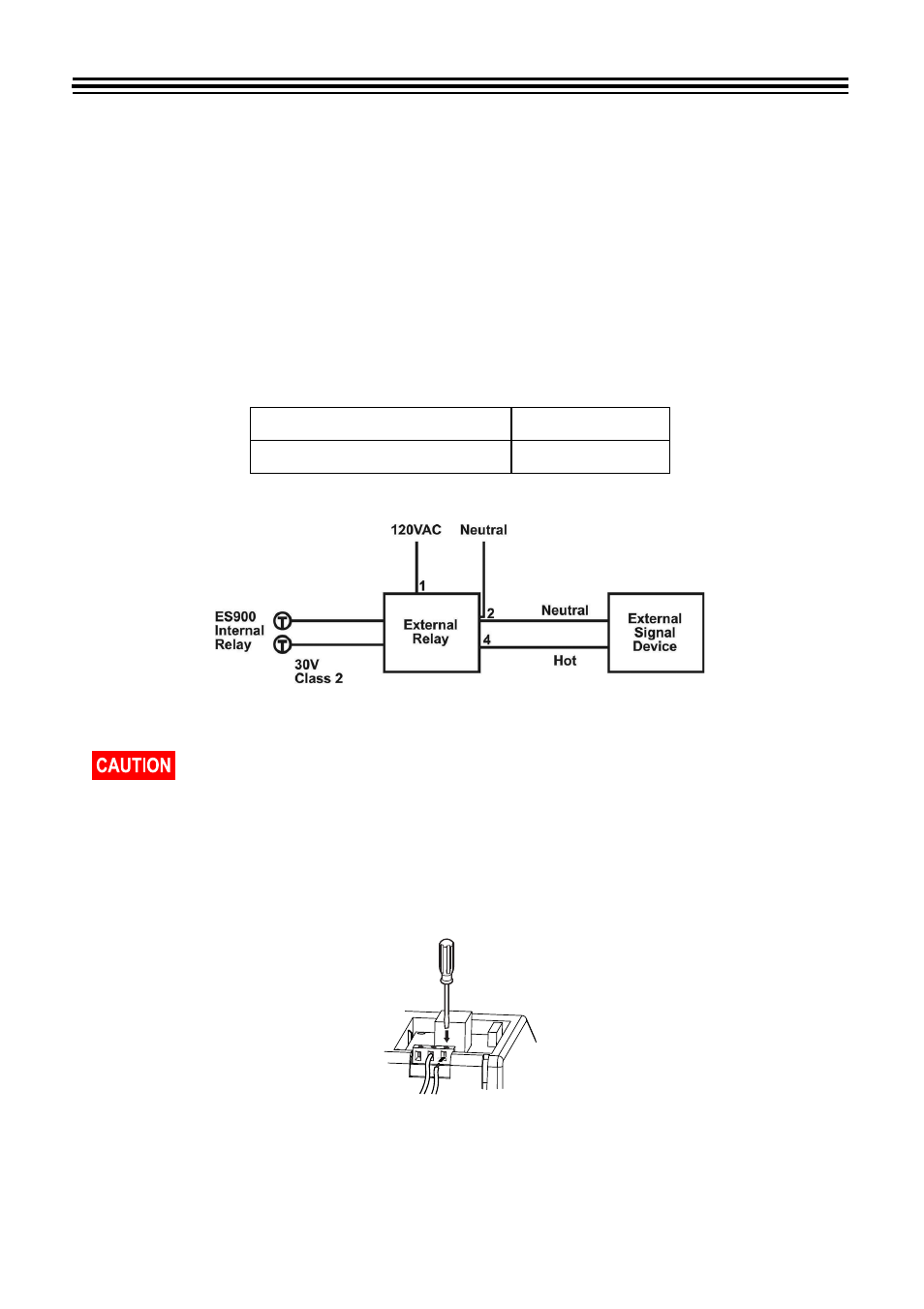
When a signal is activated, the internal contacts close completing the circuit. These internal
contacts are "dry" and supply no voltage. Voltage applied to these contacts must not exceed 30
volts. An external relay must be used to activate signaling devices.
Recommended Relay and Signal Control Board
Connections
1. Open the unit. Refer to
2. Insert wires into two right terminals for external time signal and tighten both screws. Refer to
Insert Wires into Right Terminals
below.
Insert Wires into Right Terminals
Acroprint Relay
P/N: 01-0230-000
Acroprint Signal Control Board P/N: 10-0164-000
Be sure to unplug the unit from the wall outlet before connecting wires of the External
Time Signal. Improper connection may cause a malfunction of the unit. Also refer to
“Attaching the Wire Clamp” on page 57
to secure wires with the wire clamp.