Acnodes PC 8177 User Manual
Page 16
Pin
Pin
Signal
1
10
Data Carrier Detect (DCD)
2
11
Receive Data (RXD)
3
12
Transmit Data (TXD)
4
13
Data Terminal Ready (DTR)
5
14
Ground (GND)
6
15
Data Set Ready (DSR)
7
16
Request to Send (RTS)
8
17
Clear to Send (CTS)
9
18
Ring Indicator (RI)
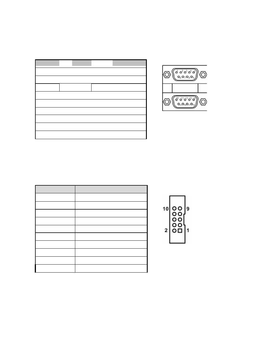
Pin
Signal
1
Data Carrier Detect (DCD)
2
Data Set Ready (DSR)
3
Receive Data (RXD)
4
Request to Send (RTS)
5
Transmit Data (TXD)
6
Clear to Send (CTS)
7
Data Terminal Ready (DTR)
8
Ring Indicator (RI)
9
Ground (GND)
10
NC
2.2.4
COM1&COM2 C onnector
The CN15 is a double-deck DB-9 connector. The upper connector (CN15A) is for COM1
and the lower connector (CN15B) is for COM2. Note that the connectors (CN13 and
CN15A) come with power capability on DCD and RI pins by setting jumpers (see section
2.2.1).
CN15A (COM1)
CN15B (COM2)
2.2.5
COM3 & COM4 C onnectors
The COM3 and COM4 i nterfac es are av aila ble through CN13 an d CN14,
r espec tiv ely. Eac h o f thes e c onnec tors is a 2x 5 pi n 2.0 pitc h b ox header, see
table bel ow for its pin a ss ignm ents .
CN13/CN14