Rmc 7155 – Acnodes RMC 7155 User Manual
Page 29
RMC 7155
14” short depth server
29
© Copyright 2011 Acnodes, Inc.
All rights reserved. Product description and product specifications
are subject to change without notice. For latest product information,
please visit Acnodes’ web site at www.acnodes.com.
14628 Central Blvd,
Chino, CA91710
tel:909.597.7588, fax:909.597.1939
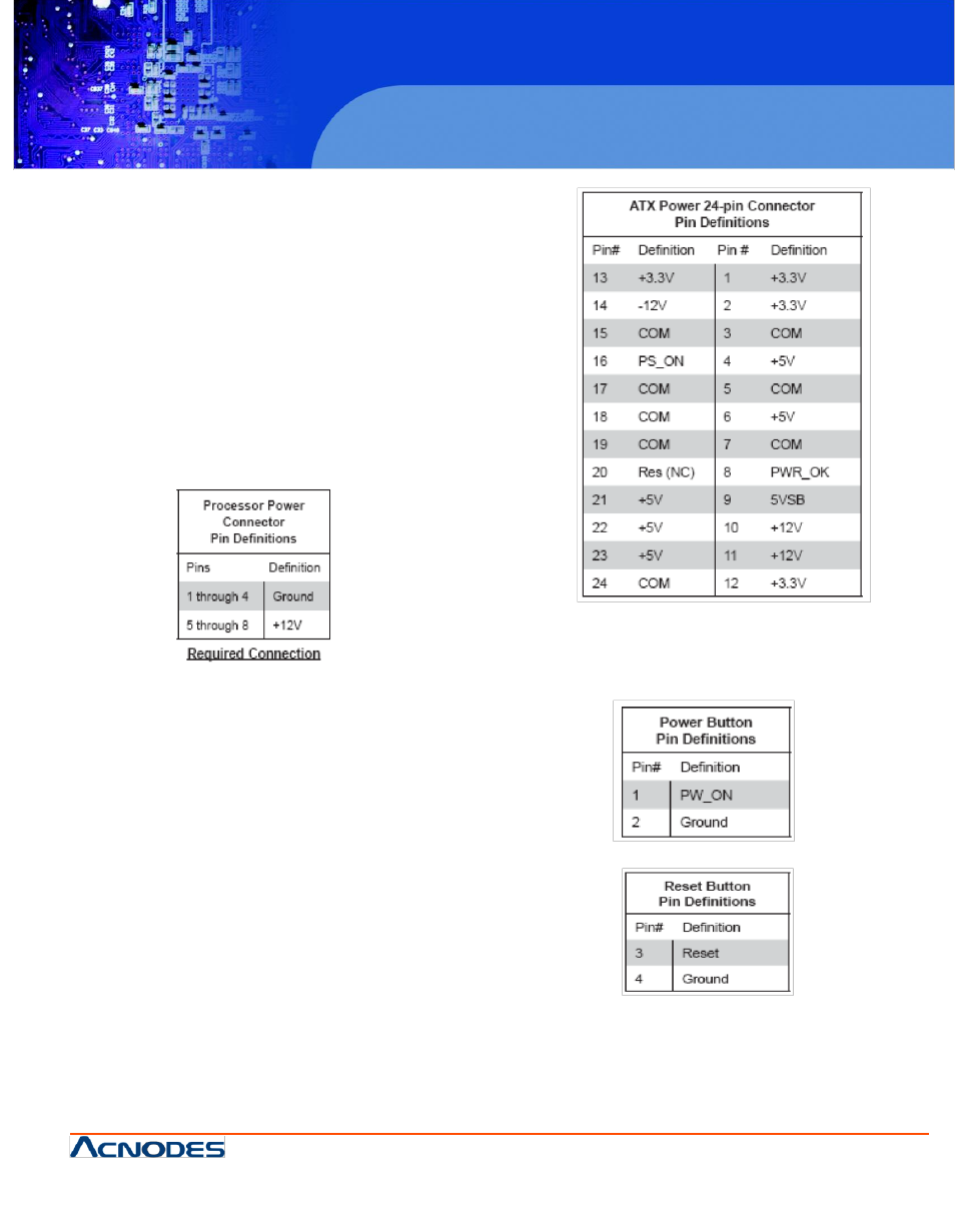
5.9 Connector Definitions
ATX Power Connector
The primary power supply connector meets the SSI
EPS 12V specification. Refer to the table on the right
for the pin definitions of the ATX 14-pin power connector.
You must also connect the 8-pin processor power
connectors to your power supply.
Processor Power Connector
In addition to JPW 1, the 12V 8-pin processor power
connectors at JPW 2 and JPW 3 must be connected
to your serverboard. Failure in doing so will void the
manufacturer warranty on your power supply and
serverboard.
PW _ON Connector
The PW _ON connector is on pins 1 and 2 of JF1.
This header should be connected to the chassis
power button. See the table on the right for pin
definitions.
Reset Connector
The reset connector is located on pins 3 and 4 of
JF1 and attatches to the reset switch on the
computer chassis.