Dmx control mode(dmx addressing), Auto control mode, Manual control mode – Acclaim Lighting X-Chip Driver IR User Manual
Page 6: Page 6
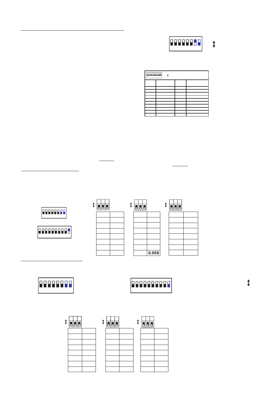
2.DMX Control Mode(DMX Addressing)
DMX is short for Digital Multiplex. This is a universal binary language used as a form of communication between
intelligent fixtures. Each Dip Switch(10-way Addressing Dip Switch) represents a binary value.
A DMX value(address) is set by combining the different dipswitches that will add up to the value you wish to achieve,
for example:
Setting DMX address for 21.
Flip switches1,3,&5 to the
"ON" position
Setting DMX address for 201.
Flip switches1,4,7,& 8 to the
"ON" position
Dipswitches# Value
1=1
3=4
5=16
=21
Dipswitches# Value
1=1
4=8
7=64
8=128
=201
In this mode, the dip-switch 7 is flipped to the "ON" position
the dip-switch 8(8-way function Dip Switch) is to the "OFF"
position. And these switches sometimes used to activate a
fixture special functions.
Dip Switch 1 address equals 1
Dip Switch 2 address equals 2
Dip Switch 3 address equals 4
Dip Switch 4 address equals 8
Dip Switch 5 address equals 16
Dip Switch 6 address equals 32
Dip Switch 7 address equals 64
Dip Switch 8 address equals 128
Dip Switch 9 address equals 256
Dip Switch 10 address equals 512
1,2,4
3,4
1,3,4
2,3,4
1,2,3,4
1
2
1,2
3
1,3
2,3
1,2,3
4
1,4
2,4
SWITCHES ON
SWITCHES ON
START
CH#
START
CH#
1
2
3
4
5
6
7
8
9
10
11
12
13
14
15
..
..
..
..
..
..
1 2
3
4
5
6
7
8
9 10
3.AUTO Control Mode
In this mode, the dip-switch 7 and 8(8-way function Dip Switch) are flipped to the "OFF" position, and the dip-switch
10(10-way Addressing Dip Switch) to the "ON" position. Flip the dip-switch 1~3(10-way Addressing Dip Switch) to
select fade time, the dip-switch 4~6 (10-way Addressing Dip Switch)to select chase speed and the dip-switch 7~9 (
10-Way Addressing Dip Switch) to select built-in 8 patterns. Their details can be referred to the below table;
000
100
010
1
2
3
7 8 9
110
001
101
011
111
4
5
6
7
8
4 5 6
000
100
010
110
001
101
011
111
0.3S
1.3S
4.5S
16S
55S
180S
512S
000
100
010
110
001
101
011
111
0%
100%
1 2 3
14%
28%
43%
57%
71%
86%
"0" = "OFF" position
"1" = "ON" position.
In this mode, the dip-switch 7 and 8(8-way Function Dip Switch) are flipped to the "OFF" position, and the dip-switch
10(10-way Addressing Dip Switch) to the "OFF" position.
000
100
010
110
001
101
011
111
0%
100%
14%
28%
43%
57%
71%
86%
"0" = "OFF" position
"1" = "ON" position.
4.1. RGB output mode enables, flip the dip-switch 1~3(10-way Addressing Dip Switch) to adjust Red color, the dip
-switch 4~6(10-way Addressing Dip Switch) to adjust Green color, the dip-switch 7~9(10-way Addressing Dip Switch)
to adjust Blue color. For more RGB color adjustment, please refer to the following table;
000
100
010
110
001
101
011
111
0%
100%
14%
28%
43%
57%
71%
86%
000
100
010
110
001
101
011
111
0%
100%
14%
28%
43%
57%
71%
86%
4.Manual Control Mode
-Page 6-
ON
OFF
1 =
0=
ON
OFF
1 =
0=
511
1,2,3,4,5,6,7,8,9
ON
OFF
1 =
0=
ON
OFF
1 =
0=
1 2
3
4
5
6
7
8
8-way Function Dip Switch
10-way Addressing Dip Switch
7 8 9
4 5 6
1 2 3
ON
OFF
1 =
0=
ON
OFF
1 =
0=
ON
OFF
1 =
0=
1 2
3
4
5
6
7
8
8-way Function Dip Switch
1 2
3
4
5
6
7
8
9 10
10-way Addressing Dip Switch
1 2
3
4
5
6
7
8
9 10
..
..
1 2
3
4
5
6
7
8
ON
OFF
1 =
0=
(10-way Addressing Dip Switch)
(8-way Function Dip Switch)
ON
OFF
1 =
0=