Acclaim Lighting X-Power HP Pro User Manual
X-power-hp-pro, Instruction manual, Appendix: system connection diagram -9
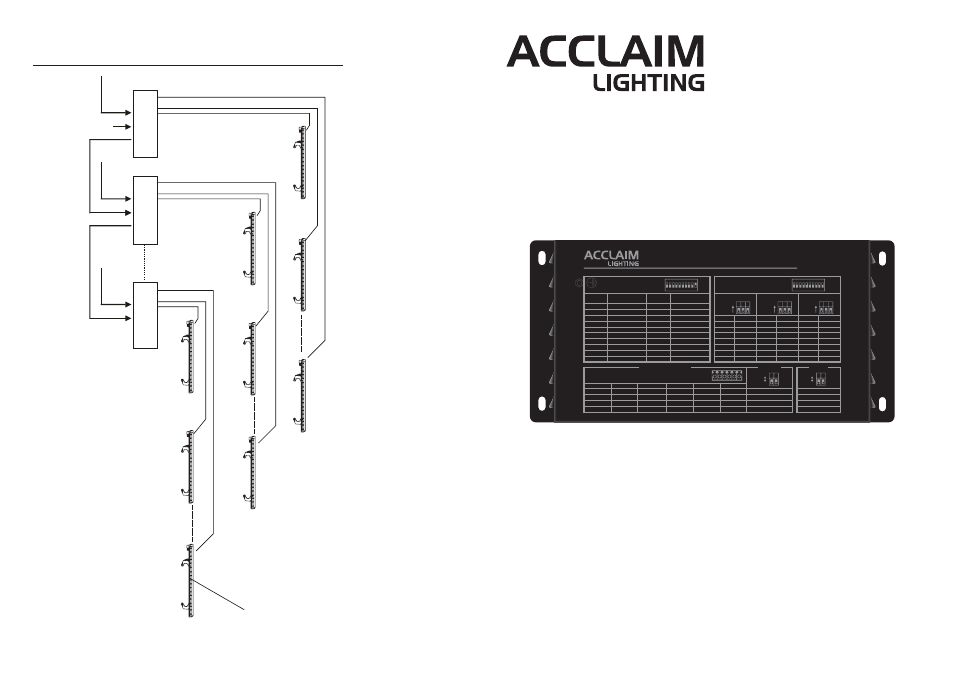
7.Appendix: System Connection Diagram
-9-
EXAMPLE 1: Detail wiring diagram for High Power LED Bar system
1
2
6
1
2
6
1
2
6
90-240VAC,
50/60Hz.
DMX IN
1
2
6
90-240VAC,
50/60Hz.
90-240VAC,
50/60Hz.
1
2
6
1
2
6
DMX OUT
DMX IN
DMX OUT
DMX IN
High Power LED Bar(Sold Separately)
X-Power-HP-Pro
X-Power-HP-Pro
X-Power-HP-Pro
Instruction Manual
X-Power-HP-Pro
WWW.Acclaimlighting.com
0 = OFF 1 = ON
000
100
010
110
001
101
011
111
0%
100%
1 2 3
ON
FADE TIME
000
100
010
110
001
101
011
111
0.1S
0.2S
0.5S
1S
5S
10S
20S
30S
4 5 6
ON
SPEED
000
100
010
110
001
101
011
111
1
2
3
4
5
6
7
AUTO
7 8 9
ON
PROGRAM
..
..
..
..
..
..
(Dip Switches 10 = off)
STAND ALONE
1 2 3 4 5 6 7 8 9 10
ON
RS
1,2,4
3,4
1,3,4
2,3,4
1,2,3,4
1,2,3,4,5,6,7,8,9
1
2
1,2
3
1,3
2,3
1,2,3
4
1,4
2,4
SWITCHES ON
SWITCHES ON
START
CH#
START
CH#
1
2
3
4
5
6
7
8
9
10
11
12
13
14
15
..
511
..
..
..
..
..
..
..
DMX ADDRESS (SLAVE)
(Dip Switches 10 = on)
1 2 3 4 5 6 7 8 9 10
ON
RS
MODE
OUTPUT
00
1 Group
10
2 Group
01
3 Group
11
6 Group
OUTPUT TERMINALS
4
5
1 =ON
0=OFF
1
2
1 =ON
0=OFF
00
RGB
10
White
01
White
Warm
11
RGB
&
1
Red +
White +
Warm White +
Red +
2
Red -
White -
Warm White -
Red -
3
Green +
White +
White +
Green +
4
Green -
White -
White -
Green -
5
Blue +
White +
Warm White +
Blue +
6
Blue -
White -
Warm White -
Blue -
1
2
3
4
5
6
Acclaim Lighting - Los Angeles, CA 90040
www.acclaimlighting.com
X-POWER-HP-PRO
X-POWER-HP-PRO
P/N: 24-004-2625-00
Draft copy (Rev1.0)