Dmx signal, No. of units / 24vdc,6.5a power supply, Page 2 – Acclaim Lighting X-Chip Driver IR User Manual
Page 2: Remote controller, Color rainbow flat-cable, Ir eye(sensor), Led remote, X-chip-driver-ir
L
E
D
R
e
m
o
te
C
o
n
tr
o
lle
r
Ye
llo
w
M
ag
en
ta
A
m
b
er
G
re
en
B
lu
e
W
h
ite
A
u
to
B
rig
ht
ne
ss
S
p
ee
d
G
re
e
n
P
at
te
rn
R
e
d
Fa
d
e
B
lu
e
R
ed
C
y
an
U
nit
S
et
tin
g
O
n
/O
ff
LED
Remote Controller
Yellow
Magenta
Amber
Green
Blue
White
Auto
Brightness
Speed
Green
Pattern
Red
Fade
Blue
Red
Cyan
Unit
Setting
On/Off
AC INPUT
100-240VAC
2
1.5mm power cable
S
ta
n
d
a
rd
D
M
X
c
a
b
le
5-color rainbow Flat-cable
O
N
1
0
9
8
7
6
5
4
3
2
1
O
N
8
7
6
5
4
3
2
1
X-CHIP Driver IR
Power/Data supply
IR in
1
2
3
4
5
6
7
8
GND
+24V
G
R
B
GND
+24V
G
R
B
GND
+24V
G
R
B
GND
+24V
G
R
B
GND
+24V
G
R
B
GND
+24V
G
R
B
GND
+24V
G
R
B
GND
+24V
G
R
B
Power in
Power out
G
N
D
+
2
4
V
+
2
4
V
G
N
D
DMX in
G D- D+
DMX out
G D- D+
D
M
X
a
d
d
re
ss
s
et
ti
n
g
M
o
d
e
Group
RGB/C&B/Color
/single
XB-R1/DMX/Manual
auto control
DMX Signal
Power Supply
12-24VDC, 24A Max.
IR EYE(Sensor)
R
e
d
B
la
c
k
W
h
it
e
R
e
d
B
la
c
k
W
h
it
e
DMX OUT
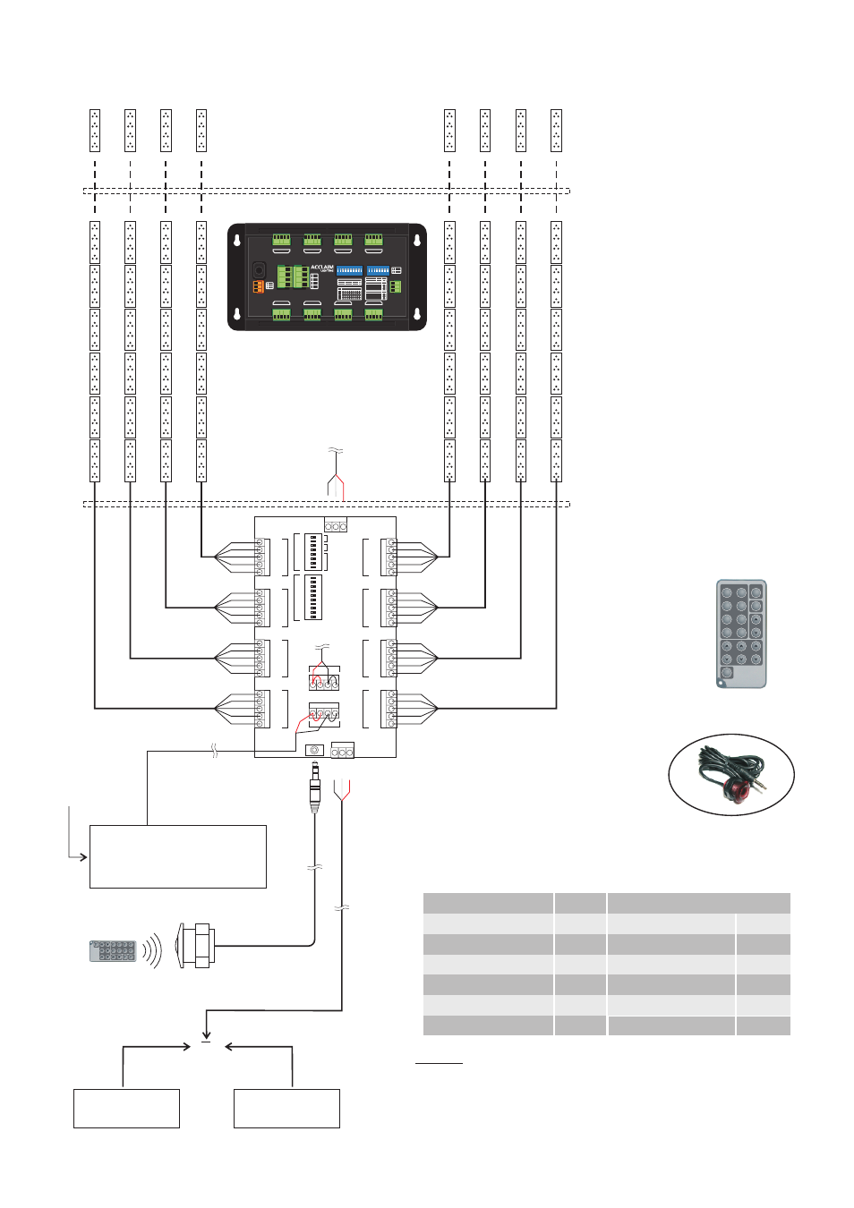
NOTE:
1.Providing the tension of 12-24VDC, 24A max can drive up to 50pcs
X-CHIP PCB modules per port, the maximum of 400pcs per X-CHIP
Driver IR in total.
2.Each PSU of 12-24VDC, 6.5A max can drive up 50pcs X-CHIP PCB
modules per port, 120pcs per X-CHIP-DRIVER-IR in total.
LED REMOTE
Connecting the X-CHIP LED PCB modules to the X-CHIP-DRIVER-IR:
DMX Controller
XB-R1
A Setup Tool
Or
No. Of units / 24VDC,6.5A power supply
X-CHIP-W15 - Amber
X-CHIP-W12 - 6000K
X-CHIP-W12 - 3200K
X-CHIP-W12 - Amber
X-CHIP-II
120
170
170
170
84
X-CHIP-100 DIP
X-CHIP-100 SMD
X-CHIP-300 DIP
X-CHIP-300 SMD
X-CHIP-W15 - 6000K
X-CHIP-W15 - 3200K
120
MODEL
QTY.
120
120
120
120
120
MODEL
QTY.
IR EYE(Sensor)
LED Remote
Accessories:
5-color rainbow Flat-cable
-Page 2-
X-Chip-Driver-IR
ON
RS
1 2 3 4 5 6 7 8 9 10
ON
RS
1 2 3 4 5 6 7 8
DMX IN
DMX Out
Power IN
DC12V-24V
Power Out
MAX 6.5A
DMX Address
X- C h i p - D r i v e r - I R
Mode
3
2
1 GND
Data -
Data +
V+
V+
GND
GND
1
2
3
4
1 2 3 4 5 6 7 8 9 10
DMX Control
001
002
511
512
1
2
3
4
5
6
7
8
9
10
Stand Alone
Red
Fade
green
speed
blue
prog
1
2
3
4
5
6
7
8
Group
5
6
RGB
C&B
Color
Single
XB-R1 Control
DMX Control
Manual
Auto
7
8
ON
OFF
+
G
R
B
GND
+
G
R
B
GND
+
G
R
B
GND
+
G
R
B
GND
+ G R B
GND
+ G R B
GND
+ G R B
GND
+ G R B
GND
Out 5
Out 6
Out 7
Out 8
Out 1
Out 2
Out 3
Out 4
Ext. IR
Sensor