Notes, Functional description, Address setting – Bosch FLM-420-EOL2W-W EOL Module LSN User Manual
Page 12: Connection
12
en
FLM-420-EOL2W-W
F.01U.100.209 | 4.0 | 2010.12
Bosch Sicherheitssysteme GmbH
Notes
Functional description
The FLM-420-EOL2W-W EOL Module LSN detects LSN line faults according to EN 54-13 and
reports them to the fire panel via LSN. The reports are displayed on the panel controller.
Address setting
Address setting is carried out using the 8 DIP switches and a suitable pointed object.
Connection
-
The power supply connection terminals are only used to connect the loose cable ends.
They are not connected to one another and are not monitored.
-
There should be an EOL module at each end of the LSN bus. This applies for stub and T-
tap cabling. These EOL modules cannot be used in loops.
-
Country-specific standards and guidelines must be considered during
planning.Connection conditions for the regional authorities and institutions (police, fire
service) must be maintained.
CAUTION!
Electrostatic discharge (ESD)! Electronic components could become damaged. Ground
yourself using a wrist strap or take other suitable measures.
NOTICE!
It is not permitted to use different operating modes in parallel in one stub/T-tap!
Address (A)
Operating mode
0
Stub/T-tap in LSN mode "improved version" with automatic address allocation
1 . . . 254
Stub/T-tap in LSN mode "improved version" with manual address allocation
255 = CL
Stub in "classic" LSN mode (address range: max. 127)
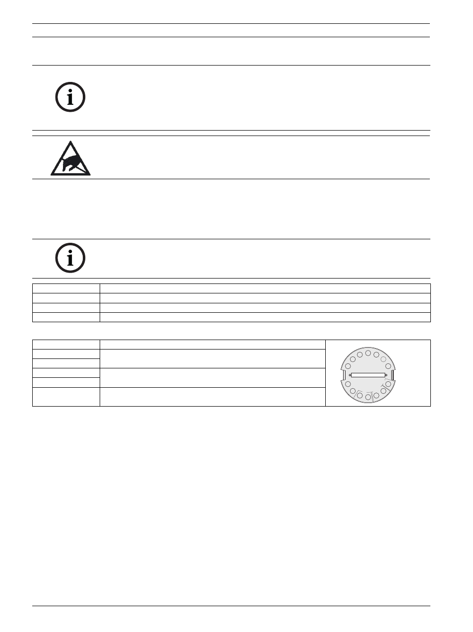
Description
Function
LSN a1-
LSN in
LSN b1+
LSN-POW 0 V
LSN power supply (if present)
LSN-POW +U
Shield
Cable shielding (if present)
>DE¦¦=GDO¦O
DKF
¦HG
O
V
0
U
+
Z¦
[¸
8
DKF
DK
F
Ka
b^
e]