Smoke index procedure, B. external pressure probe, Connect the probe to the instrument – RIDGID FG-100 User Manual
Page 7: Insert the probe to the chimney, Press, Ambient temperature probe flue gas probe
REMOVE THE PROBE FROM THE STACK
Press:
Press
to select the external Sensor input
F2
Press
“ZERO” to
.
ait for the measure stabilization.
Press
to save the measured value. The v
Press
to exit to the previous menu.
FI
F2
reset the display indication
Insert the probe inside the standard boiler holes (see figure). If the boiler
do not have them, insert the probe at 2 diameter from the boiler and in
central position in the stack
W
alue will printed on the report.
The smoke index can be set.
Connect the external probe to the instrument
ATTENTION:
be sure that the two elements, sensor and probe, are fixed
and in vertical position. Do not move the probe after the zeroing.
3. Smoke index procedure
- applicable for oil burner
REMOVE THE PROBE FROM THE STACK
Press
to input the ambient temperature
Draft can be measured using the external pressure probe.
Do not exceed 0.2 mbar input.
B. External pressure probe
–
F1=Internal sensor
F2=External sensor
TaE
23.00
INT
EXT
–
DRAUGHT
Measure
1.0 mbar
Press [ENTER]
To save measure
ZERO
ESCAPE
–
SMOKE
Meas. 1: -
Oil.Der.: NO
ESCAPE
Meas. 2: -
AVG
Meas. 3: -
-
Press
#
DP
6
To avoid condensation inside the smoke pump, aspirate ambient air
before the gas sample by the fireside (not in the exhaust gas connection
pipe) without using the paper filter. Introduce now the filter in the pump. The
gas sample should be drawn to the center of the combustion gas flux. The
correct gas volume is sampled with 10 uniform suctions from the pump.
Compare the darkening of the filter with the smoke index table.
The smoke index found cannot exceed the ones defined by the current
normative.
We suggested to use a retaining cone during gas sampling.
Select the Test (from 1 to 3) for input, pressing
to confirm the selection.
Enter value ( from 0 to 9) pressing
Execute the steps above for other test in the same way.
Press
to confirm changes.
Press:
Select the “Oil derivative” field for input, pressing
to confirm the selection.
Enter value (Yes or Not) pressing
Press
to confirm changes.
Press
to exit to the previous menu.
Values will printed on the report.
F2
Press:
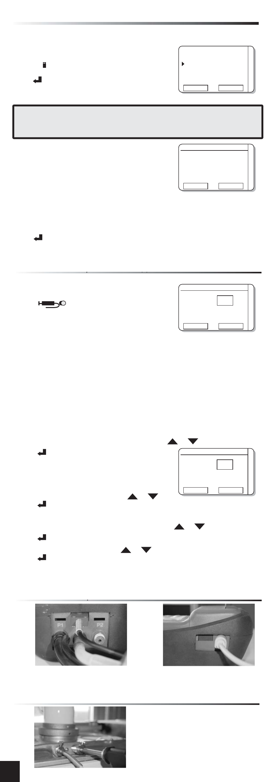
4. Connect the probe to the instrument
Ambient temperature probe
Flue gas probe
–
SMOKE
Meas. 1: 3
Oil.Der.: NO
ESCAPE
Meas. 2: 3
AVG
Meas. 3: 2
-
5. insert the probe to the chimney
Insert the probe inside the standard
boiler holes (see figure).
If the boiler do not have them, insert
the probe at twice the diameter from
the boiler and in central position in the
stack.