Operations, E. co diluted to oxygen reference, Switch the instrument on – RIDGID FG-100 User Manual
Page 6: D. engineering units, Set the right fuel for the boiler, Pressure draft procedure, A. internal pressure sensor
E. CO diluted to Oxygen reference
The CO undiluted (0% O ) setting is standard set. Use the procedure below
if a different reference value is required.
2
Select the parameter for changing, pressing
Confirm the selection pressing the key
Set
value, pressing
the reference
Confirm changes pressing the key
Press:
F1
Select and confirm the “O2 reference” option.
Wait the 60 seconds countdown
for the autozero procedure.
DO NOT INSERT THE PROBE IN THE STACK
To mute the beep
1. Switch the Instrument ON
OPERATIONS
D. Engineering units
Technical unit for gas, temperature and pressure can be set.
F1
Select the parameter for changing, pressing
Confirm the selection pressing the key
Set
value, pressing
Day , Month or Year
Confirm changes pressing the key
Press:
5
ATTENTION:
Be sure that the boiler room is well vented and secure from CO.
Before entring in the boiler room check the ambient CO concentration.
–
ENGINEER UNITS
> CO
ppm
Other
ppm
Temp.
°C
Pres.
hPa
ESCAPE
The fuels can be changed.
Up to 10 fuels can be set using GasConfig PC software and the USB cable.
Select the Fuel from a list pressing
Confirm the selection pressing the key
Press:
Select and confirm the “--- FUEL ---” option.
1. Set the right fuel for the boiler
Press
(F2) to start the flue gas analysis
ESCAPE
6
To pause the analysis press the
button. This will stop the internal
pump. Press
(F2) to restart the flue gas analysis.
ESCAPE
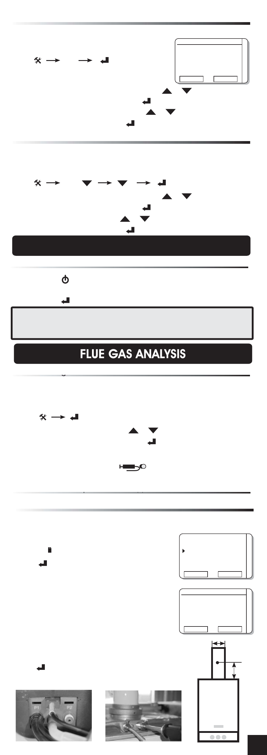
2. Pressure Draft procedure
- applicable for natural draft boiler
REMOVE THE PROBE FROM THE STACK
A. Internal pressure sensor
Differential pressure and draft can be measured using the internal
pressure sensor (P1 - P2) inlet. Do not exceed 200mbar input.
Press
to select the Internal Sensor input
F1
Press
to input the ambient temperature
Press
“ZERO” to reset the display indication.
Wait for stabilization of the measurement.
Press
to save the measured value.
Value will printed on the report.
Press
to exit to the previous menu.
FI
F2
Insert the probe inside the standard
boiler holes (see figure). If the boiler do not have
them, insert the probe as shown in the drawing.
2 x D
D
–
F1=Internal sensor
F2=External sensor
TaE
23.00
INT
EXT
–
DRAUGHT
Measure
1.0 mbar
Press [ENTER]
To save measure
ZERO
ESCAPE
Press
#
DP