Devicenet network scanner dvpdnet-sl – 2nd Ave. DVPDNET-SL DeviceNet Network Scanner DVP-0204520-02 User Manual
Page 21
DeviceNet Network Scanner DVPDNET-SL
DVP-PLC Operation Manual
19
Target
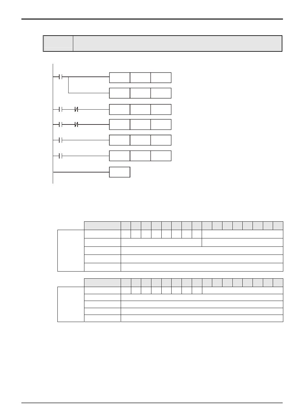
When X0 = On, VFD-B will start to run, and Y0 indicator will be On.
When X1 = On, VFD-B will stop, and Y0 indicator will be Off.
1. PLC
program:
MOV
H2
D6288
M1000
MOV
D6038
K4M20
M8
MOV
H1
D6288
MOV
H0100
D6287
MOV
H0000
D6287
MOV
D6037
K4M0
M9
M8
M9
M20
M21
END
Send the content in D6037 to K4M0.
Send the content in D6038 to K4M20.
When X0 = On, start VFD-B.
When X1 = On, stop VFD-B.
When VFD-B runs, Y0 = On.
When VFD-B stops, Y0 = Off.
2. Program
explanations:
The head instruction in the program, MOV, corresponds the content in D6037 to M0 ~ M15 and the
content in D6038 to M20 ~ M35.
See the table below for the corresponding relation between DeviceNet slave and PLC devices.
PLC device
15 14 13 12
11
10
9
8
7
6
5
4
3
2
1
0
D6037 X7 X6 X5 X4 X3 X2 X1 X0
N/A
D6038
Status of VFD-B
Status of LED on VFD-B
D6039
Frequency of VFD-B
D6040
Input
data
…
PLC device
15 14 13 12
11
10
9
8
7
6
5
4
3
2
1
0
D6287 Y7 Y6 Y5 Y4 Y3 Y2 Y1 Y0
N/A
D6288
Control word in VFD-B
D6289
Frequency in VFD-B
D6290
Output
data
…
When X0 = On, b8 of D6037 = 1. b8 of D6037 corresponds to M8, and therefore M8 = On. That is,
when X1 = On, M9 will be On.
D6288 corresponds to the control word in VFD-B. When M8 = On, execute [MOV H2 D6288] to run
VFD-B. When M9 = On, execute [MOV H1 D6288] to stop VFD-B.
b0 of D6038 corresponds to M20, b1 to M21, and so on. When VFD-B is in RUN status, b0 of D6038 =
1 and M20 will be On to execute [MOV H0100 D6287], which leads to Y0 = On. That is, when
VFD-B is in STOP status, M21 will be On to execute [MOV H0000 D6287], which leads to Y0 = Off.