Devicenet network scanner dvpdnet-sl, 4 configuration – 2nd Ave. DVPDNET-SL DeviceNet Network Scanner DVP-0204520-02 User Manual
Page 10
DeviceNet Network Scanner DVPDNET-SL
DVP-PLC Operation Manual
8
DVPDNET
35mm DIN rail
DVP28SV
RUN
STOP
3.3
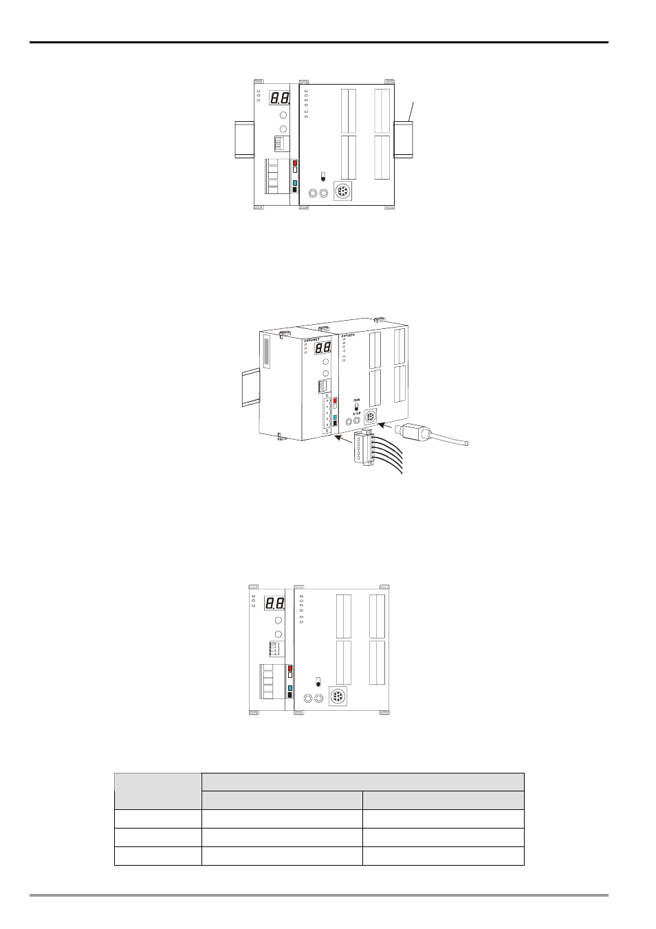
Connecting to DeviceNet Connection Port
The colors on the PINs on the DeviceNet connection port match the colors of the connection cables.
Make sure you connect the cable to the right PIN.
We recommend you also apply Delta’s power module in the connection.
4 Configuration
4.1
Corresponding Relation between DVPDNET-SL and DVP-SV
After all DVPDNET-SL are connected to DVP-SV, DVP-SV will distribute data mapping areas to every
DVPDNET-SL.
DVPDNET
DVP28SV
RUN
STOP
The index of DVPDNET-SL is its number. The first DVPDNET-SL on the left hand side of DVP-SV is No. 1,
the following DVPDNET-SL modules are No.2, No.3, No.4 and so on.
Mapped D registers
DVPDNET-SL
index
Output mapping
Input mapping
1
D6250 ~ D6497
D6000 ~ D6247
2
D6750 ~ D6997
D6500 ~ D6747
3
D7250 ~ D7497
D7000 ~ D7247