Connecting the chassis ground, Warning: shock hazard – Xantrex Technology 1000 User Manual
Page 31
Installation
3–12
975-0127-01-01
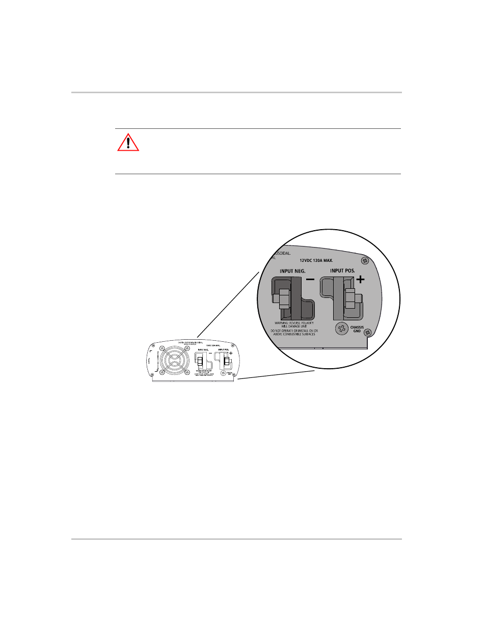
Connecting the Chassis Ground
The XPower 1000 has a screw terminal labelled
CHASSIS GND
on the
rear panel as shown in Figure 3-3 on page 3–12. Follow the guidelines in
“Grounding Locations” to connect the inverter’s chassis to the ground.
Grounding Locations
You must connect the chassis ground terminal to a grounding point. The
grounding point varies depending on where you install the XPower 1000.
•
For recommended chassis ground cable size, see Table ,
“Calculating Size of Chassis Ground Cable” on page 3–7.
Follow the instructions that correspond to your type of installation:
To connect the chassis ground terminal to a grounding point:
•
Recreational Vehicle: Connect the
CHASSIS GND
screw to the
vehicle’s chassis using recommended copper wire (if insulated then
green insulation with or without one or more yellow stripes) or larger.
WARNING: Shock hazard
Never operate the XPower 1000 without properly connecting the chassis
ground. Electrical shock hazard could result from improper grounding.
Figure 3-3 DC Panel Connections