Dyna. phaser, Rev+chorus, Rev → chorus – Yamaha DSP5D User Manual
Page 329
PM5D/PM5D-RH V2 / DSP5D Owner’s Manual
Reference section
329
Information shown
in the display
Function
menu
Global
functions
Output
functions
Input
functions
Appendices
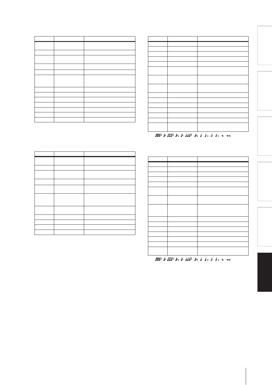
❏ DYNA. FLANGE
Two input, two output dynamically controlled flanger.
❏ DYNA. PHASER
Two input, two output dynamically controlled phaser.
❏ REV+CHORUS
One input, two output reverb and chorus effects in parallel.
❏ REV→CHORUS
One input, two output reverb and chorus effects in series.
Parameter
Range
Description
SOURCE
INPUT, MIDI
Control source: input signal or
MIDI Note On velocity
SENSE
0–100
Sensitivity
DIR.
UP, DOWN
Upward or downward frequency
change
DECAY
*1
*1. 6.0 ms–46.0 s (fs=44.1 kHz), 5.0 ms–42.3 s (fs=48 kHz),
3 ms–23.0 s (fs=88.2 kHz), 3 ms–21.1 s (fs=96 kHz)
Decay speed
OFFSET
0–100
Delay time offset
FB.GAIN
–99 to +99%
Feedback gain (plus values for
normal-phase feedback, minus
values for reverse-phase feedback)
LSH F
21.2 Hz–8.00 kHz
Low shelving filter frequency
LSH G
–12.0 to +12.0 dB
Low shelving filter gain
EQ F
100 Hz–8.00 kHz
EQ (peaking type) frequency
EQ G
–12.0 to +12.0 dB
EQ (peaking type) gain
EQ Q
10.0–0.10
EQ (peaking type) bandwidth
HSH F
50.0 Hz–16.0 kHz
High shelving filter frequency
HSH G
–12.0 to +12.0 dB
High shelving filter gain
Parameter
Range
Description
SOURCE
INPUT, MIDI
Control source: input signal or
MIDI Note On velocity
SENSE
0–100
Sensitivity
DIR.
UP, DOWN
Upward or downward frequency
change
DECAY
*1
*1. 6.0 ms–46.0 s (fs=44.1 kHz), 5.0 ms–42.3 s (fs=48 kHz),
3 ms–23.0 s (fs=88.2 kHz), 3 ms–21.1 s (fs=96 kHz)
Decay speed
OFFSET
0–100
Lowest phase-shifted frequency
offset
FB.GAIN
–99 to +99%
Feedback gain (plus values for
normal-phase feedback, minus
values for reverse-phase feedback)
STAGE
2, 4, 6, 8, 10, 12,
14, 16
Number of phase shift stages
LSH F
21.2 Hz–8.00 kHz
Low shelving filter frequency
LSH G
–12.0 to +12.0 dB
Low shelving filter gain
HSH F
50.0 Hz–16.0 kHz
High shelving filter frequency
HSH G
–12.0 to +12.0 dB
High shelving filter gain
Parameter
Range
Description
REV TIME
0.3–99.0 s
Reverb time
INI. DLY
0.0–500.0 ms
Initial delay before reverb begins
HI. RATIO
0.1–1.0
High-frequency reverb time ratio
DIFF.
0–10
Spread
DENSITY
0–100%
Reverb density
HPF
THRU, 21.2 Hz–
8.00 kHz
High-pass filter cutoff frequency
LPF
50.0 Hz–16.0 kHz,
THRU
Low-pass filter cutoff frequency
REV/CHO
0–100%
Reverb and chorus balance (0% =
all reverb, 100% = all chorus)
FREQ.
0.05–40.00 Hz
Modulation speed
AM DEPTH 0–100%
Amplitude modulation depth
PM DEPTH
0–100%
Pitch modulation depth
MOD. DLY
0.0–500.0 ms
Modulation delay time
WAVE
Sine, Tri
Modulation waveform
SYNC
OFF/ON
Tempo parameter sync on/off
NOTE
*1
*1.
Used in conjunction with TEMPO
to determine FREQ.
Parameter
Range
Description
REV TIME
0.3–99.0 s
Reverb time
INI. DLY
0.0–500.0 ms
Initial delay before reverb begins
HI. RATIO
0.1–1.0
High-frequency reverb time ratio
DIFF.
0–10
Spread
DENSITY
0–100%
Reverb density
HPF
THRU, 21.2 Hz–
8.00 kHz
High-pass filter cutoff frequency
LPF
50.0 Hz–16.0 kHz,
THRU
Low-pass filter cutoff frequency
REV.BAL
0–100%
Reverb and chorused reverb bal-
ance (0% = all chorused reverb,
100% = all reverb)
FREQ.
0.05–40.00 Hz
Modulation speed
AM DEPTH 0–100%
Amplitude modulation depth
PM DEPTH
0–100%
Pitch modulation depth
MOD. DLY
0.0–500.0 ms
Modulation delay time
WAVE
Sine, Tri
Modulation waveform
SYNC
OFF/ON
Tempo parameter sync on/off
NOTE
*1
*1.
Used in conjunction with TEMPO
to determine FREQ.